We are extending LANs out to transmitter sites for many reasons; backup audio, control and monitoring, security systems, VOIP phones, etc.
I am casually (very casually) toying around with creating my own Linux-based remote control system. The ongoing Windows 10 upgrade debacle continues to not end, I can’t help but think that there are many potential clients who could use a reliable transmitter/studio remote control and monitoring system based on a stable operating system. Hmm, sounds like a sales pitch 😉
Anyway, I have run across several Ethernet board manufacturers that offer a variety of boards with 8-12 contact closures and a variety of analog and digital inputs. Most new transmitters have some sort of web GUI which are great for transmitter control and monitoring. As we all know, there is more than just a transmitter at any given transmitter site. In addition to the transmitter, I would like to control and monitor things like tower lights, interface and control of coax switches, temperature monitoring, generator status, the old non-web interface backup transmitters, STL signal strength for those old 950 MHz links, etc.
That particular PC board is made in Bulgaria, which is home to this: Mount Buzludzha
What I like about these particular boards is the DRM software (DRM has, apparently, many different meanings) which will run on Linux or Windows. There are also iOS and Android applications that can be used as well. It appears that the GUI can be customized for various uses. This seems like it is written in Java, so perhaps I could have some Java expert customize it for radio use. It looks like up to 32 boards can be controlled by a single instance of the DRM software. Alarm reporting would be via SNMP trap and email.
I don’t know, there is one particular cluster of stations that needs new remote control gear at almost every transmitter site. Perhaps a little alpha testing is in order? It could be fun…
Alternate title: Building and ATU in a truck body toolbox.
Alternate title II: I should get paid extra for this shit.
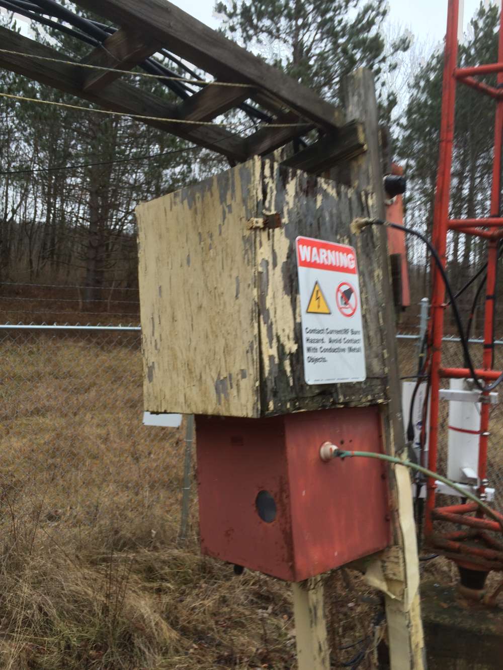
There is an AM radio station that is near death but the owners do not want it to go away. Nor do they want to spend very much money to keep it around, thus the dilemma. At the transmitter site, there is a multitude of problems; leaking roof, very old rusty ATU, rotting support posts and transmission line bridge, equipment racks rusting out, nothing is grounded properly, the building is full of junk, snakes, and mice have moved in. To further complicate things, the tower and transmitter building serves as an STL relay point for two of the market’s FM stations. There is also two translators with antennas on the tower. The ATU and tower light choke box are rusting through, which is causing arcing and broadband RF noise that is interfering with the FM station’s STL receiver. There was a homemade isocoupler for one of the translators that were allowing AM RF back into the building which was creating havoc with everything. Because of this, the AM station is currently silent. In short, it is a mess.
WCHN ATU
The red box on the bottom is the ATU, the plywood box on the top with the peeling yellow paint is the homemade isocoupler, and the tower light choke box is behind the isocoupler.
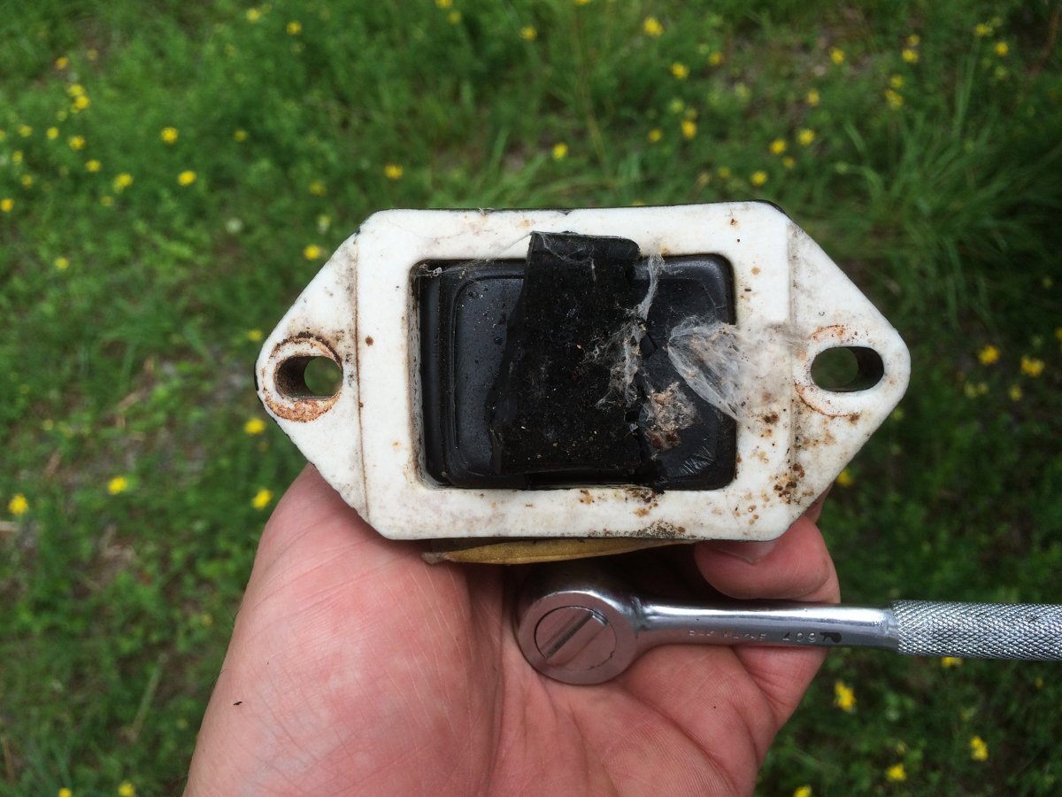
Crumbling old ATU output capacitor in series with tower
This was the capacitor that was feeding the antenna, .0041uf, 10KV 8 amps.
We started remediation on this last February, which is not the optimum time for replacing rotting wooden posts. However, we were able to clean out the building. The leaking roof has been repaired. I was able to find a few old racks from a Schafer Automation system to replace the rusted-out original racks. I began the process of grounding the equipment racks, the incoming transmission lines for the STL, etc.
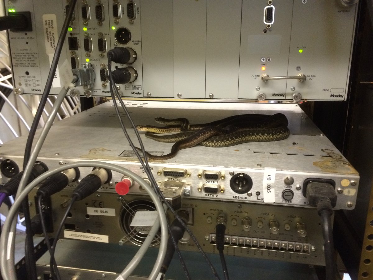
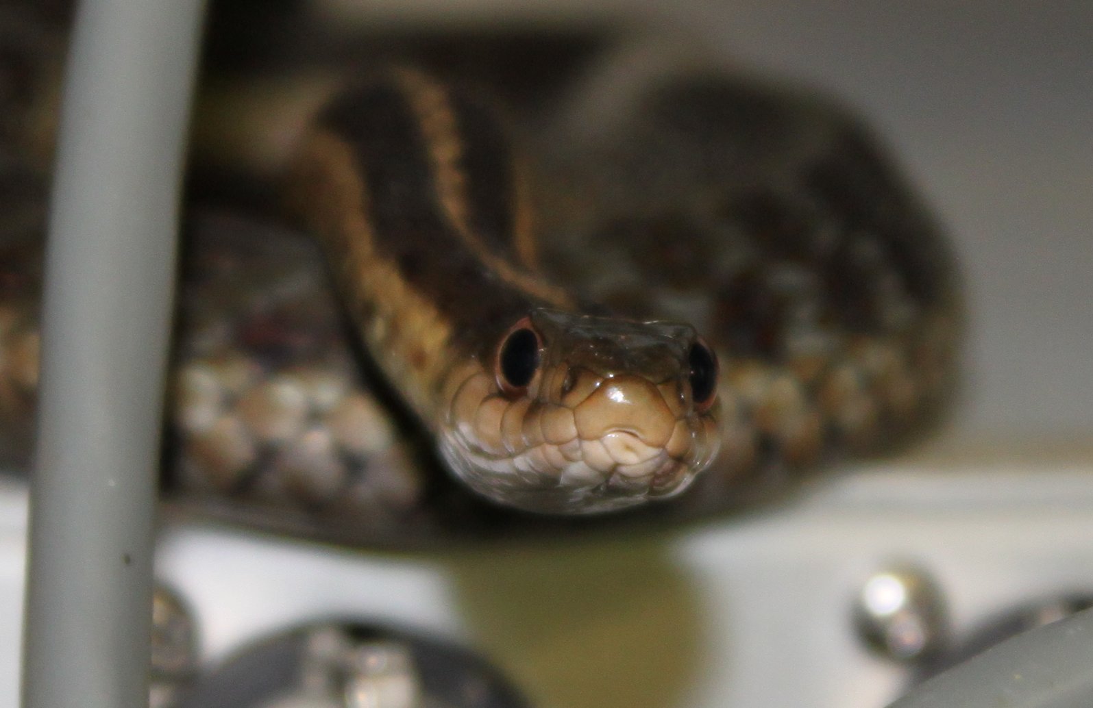
Cool morning, Garter Snakes warming themselves on top of a Moseley DSP-6000Garter Snake
We will have to find out how they are getting in, the plug up those holes.
Then there were the ATU and tower light choke enclosures. Original to the 1952 sign-on, they were past their serviceable days. Since this is all being done on a budget and nobody wants to spend money on an AM station that has little or no listeners and even less revenue, we had a problem.
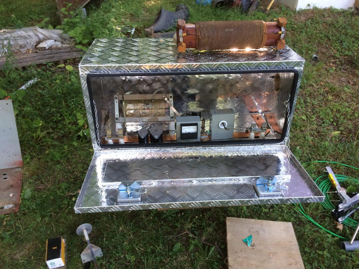
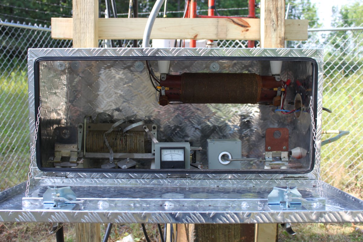
Then somebody suggested building an ATU in a truck body tool box. Well… This isn’t the Meadowlands, so if there are no other alternatives then okay, I guess. Off to Amazon to order a toolbox. This particular unit seems fine, my only comment is on the gauge aluminum (or aluminium if you prefer), which is slightly thin for holding up all those parts.
Fabrication shop, ATU built in a truck body toolbox
Still, the box itself is nice enough and certainly better than the old one. I was able to reuse the inductor and the Delta current meter but the old Sangamo capacitors crumbled in my hands when I removed them. I also saved the feed through bowls, J-plugs, and other parts. I used some copper strap to run a good RF ground from the input to the ground connection. Overall, I am pretty pleased with the finished product. It is a little bit tight in there, but this station only runs 1 KW, so it should be fine.
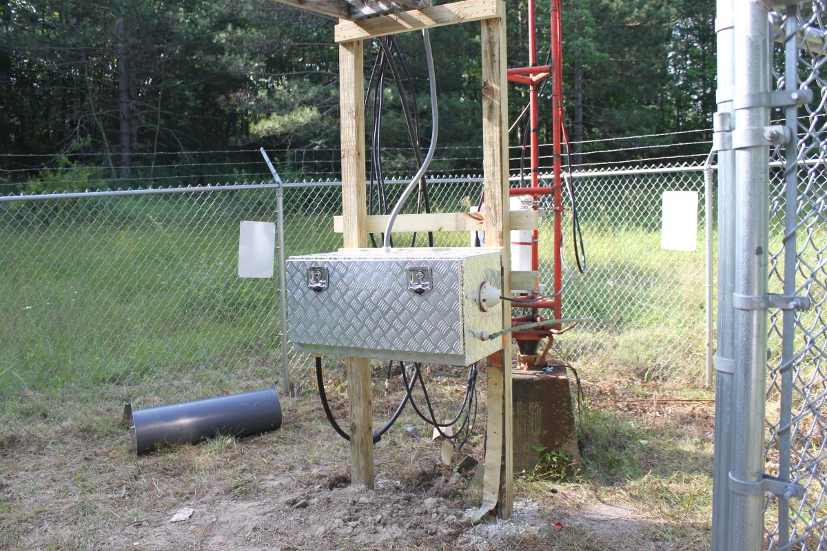
Replacement ATU mounted
So, new pressure-treated posts were installed, the box was mounted and the transmission line was connected.
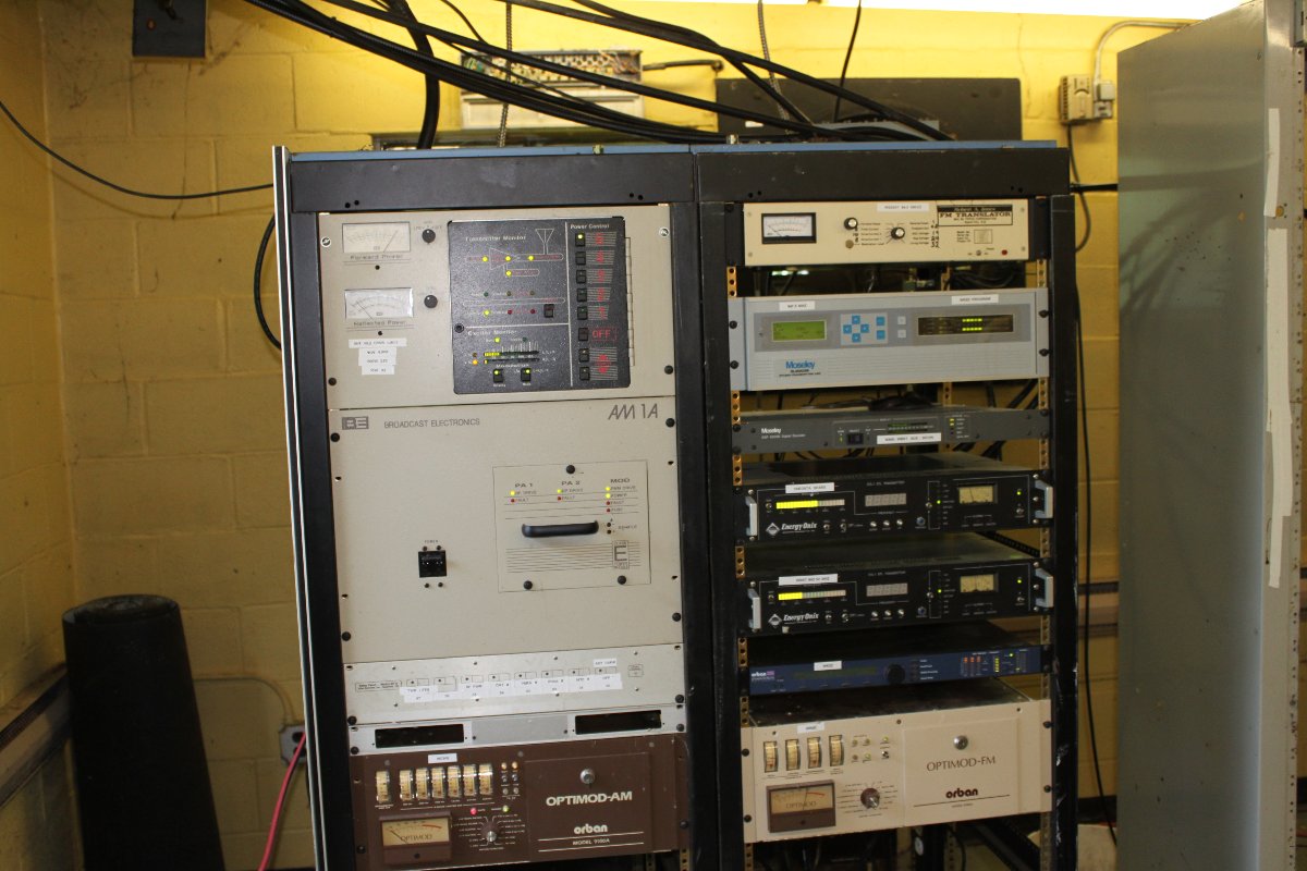
Replacement ATU under power.Reused Schafer Automation racks, much better than the 1950’s Gates racks
The reused racks are old but serviceable and a big improvement over the old, rusting-out racks. I was able to bond each rack to the ground strap that was used to connect to the RCA BTA-1 transmitter. There is one more rack to install to the right of these two. That should give us more than enough rack space for this site.
The station is back on at full power and not interfering with the FM STLs or the translators. You can actually touch the rack and not get an RF burn!
We are also working on an air conditioner.
Other work at this site; cleaning out the building, replacing the tower light photocell, installing a ground buss bar, some STL lightning protectors, dressing the transmission lines, etc. It is a work in progress.
This is a topic I have covered before, but it is worth doing it again for future reference. The previous post covered downgrading an AM transmission facility for WGHQ, Kingston, NY.
This is part II of that process.
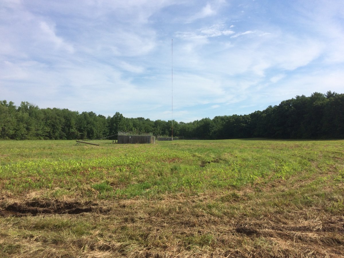
WGHQ transmitter site, towers 1 and 2 removed
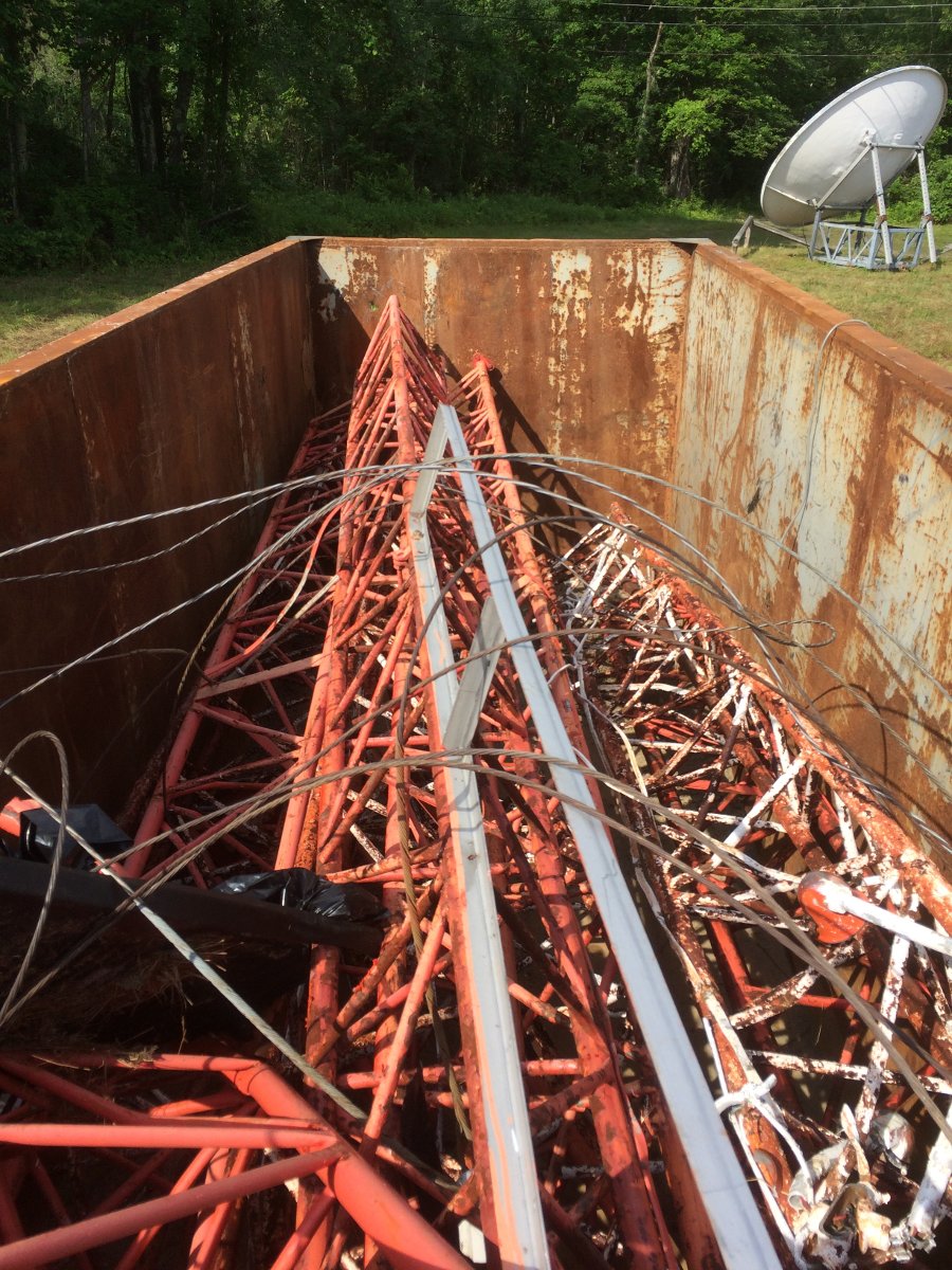
The old towers have been cut up and put in a scrap metal dumpster. They are off to China to be melted down and made into a submarine or a missile or a tank or something useful like that.
Towers scrapped
The directional array had three towers in a straight line with a common point impedance of 60 Ohms. Dropping two towers greatly changed the electrical characteristics of the remaining tower, therefore the existing ATU needed a bit of reworking to match the 50 Ohm transmitter output.
The first step, correct a few deficiencies left over from the old array.
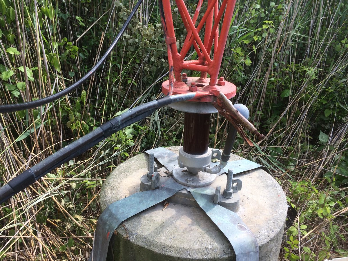
Vise grip tower feed
This vise-grip RF connection has to go. The problem is where the tower erectors attempted to solder the copper tubing. That tower base plate is pretty big and I would wager they didn’t use enough heat to make the solder connection. They were probably working in the winter time, thus the “temporary” fix. This tower was put up in 1993, so that temporary fix lasted 23 years.
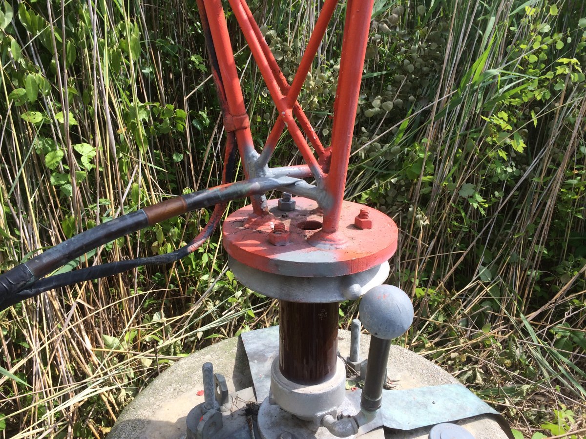
I removed the offending tool and soldered the connection to another part of the tower with silver solder. The smaller crossbar made a good connection point.
RF feed correctly connected to the tower
After soldering, I cleaned up and sprayed some grey primer on it to prevent rust from forming where I scraped the paint off.
Next, I made an impedance measurement:
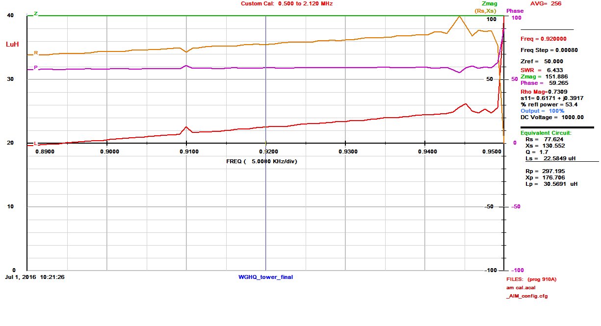
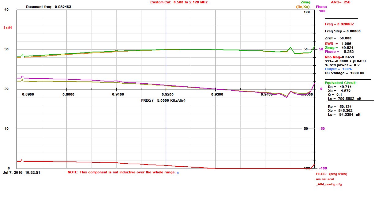
WGHQ 920 KHz tower base impedance measurement
That junk on the upper part of the graph is coming from WHVW on 950 KHz. The tower itself looks pretty good, 77.6 Ohms resistance with 130 Ohms inductive reactance. Since this is not part of a directional antenna system, the ATU design is pretty straightforward. Given that WHVW on 950 KHz is located 10.41 miles away, a low-pass filter design is optimum. A basic low pass filter T network has inductive input and output legs with a capacitive shunt leg to ground.
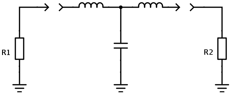
T network diagram
Each leg is used to match the 50 Ohm transmission line impedance (R1) to the 77.6 Ohm tower impedance (R2) and cancel out the 130 Ohms of inductive reactance. This is a vector impedance problem, much like a vector force problem in physics. Some basic arithmetic is required (always include the units):
X1, X2, X3 = √(Zin x Zout)
X1, X2, X3 = √(50Ω x 77.6Ω) or X = 62.28Ω
The value of inductance or capacitance for each leg is calculated using the basic inductance or capacitance formulas:
L (μH) = XL / 2πf(MHz)
And
C (μF) = 1 / 2πf(MHz) XC
Thus the input leg, or X1 = 62.28Ω / (6.28 x 0.92 MHz) or 10.78 μH
The Shunt leg, or X2 = 1 / (6.28 x 0.92 MHz x 62.28Ω) or .0028 μF
The output leg is a little different. The tower has 130 Ohms of inductive reactance that needs to be canceled out with a capacitor. Rather than cancel out all of the inductive reactance, then add an inductive output leg, the tower reactance can be used as part of the tuning circuit. The design calls for 62.28 Ohms inductive reactance, so 130Ω – 62.28Ω = 67.27Ω, which is the value needed to be canceled by a capacitor:
Output leg, or X3 = 1 / (6.28 x 0.92 MHz x 67.27Ω) or .0025 μF
A little Ohm’s law is used to calculate the base current for both the day and night time operations.
Ohm’s law pie chart calculator
Thus the daytime base current is I = √(P/R) or I = √(1000 W/77.6Ω) or 3.58 Amps.
Night time base current is I = √(38 W/77.6Ω) or 0.70 Amps
Current handling requirements:
Base current is calculated to be 3.6 Amps at 1,000 Watts carrier power. Allowing for 125% peak positive modulation makes it 5.7 Amps. Having a safety factor of two or 11.4 Amps output leg and 14 Amps input leg.
Voltages: 353 maximum input voltage, 439 output.
Thus, 20 amp, 10 KV parts should work well.
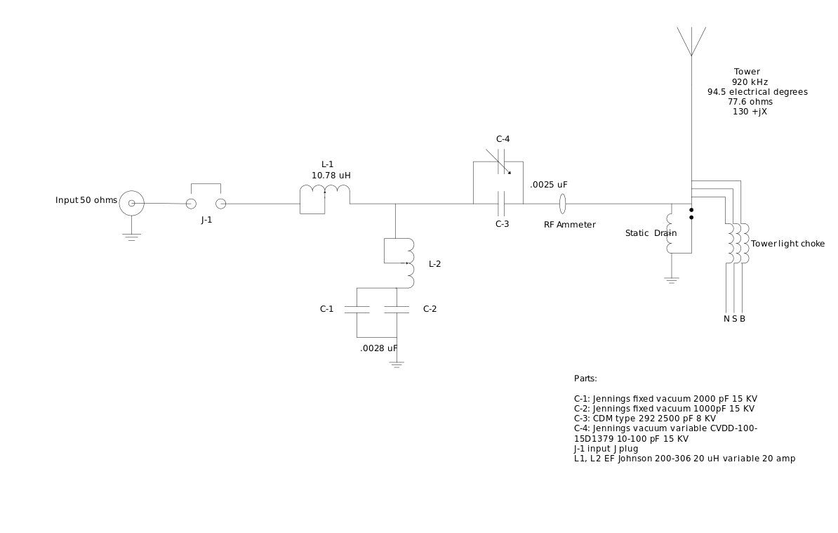
The designed schematic for the ATU:
WGHQ ATU Schematic diagram
Putting it all together.
Since the tower looks fairly broad at 920 KHz, we are going to attempt a nice broadband ATU to match it. This station is currently programmed with a classic country format, and I have to tell you; those old Conway Twitty, Merle Haggard, Patsy Cline, et al., songs sound pretty good on the old AM radio. The Subaru stock radio has HD, which also has a nice broad IF section, thus allowing all those lovely mid-high-range frequencies through.
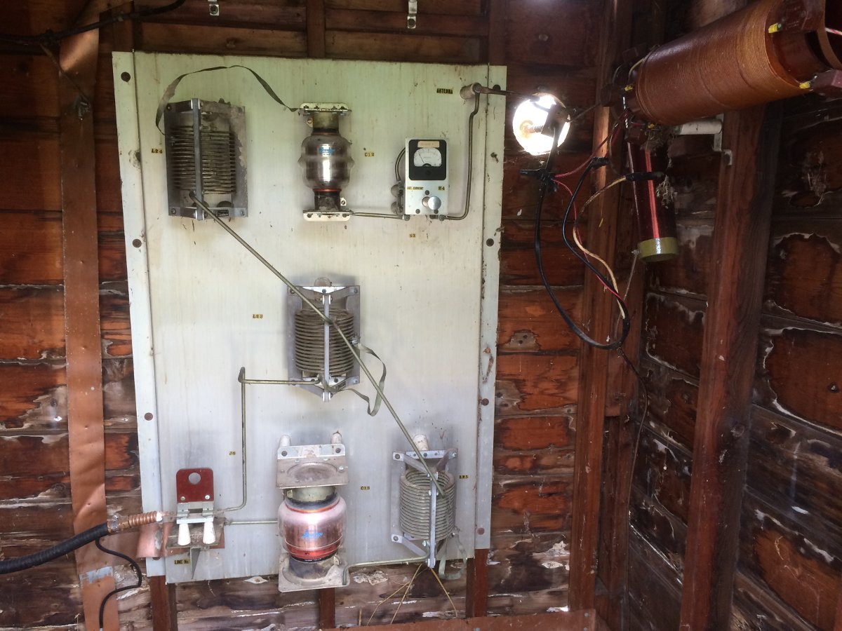
This is the existing ATU, which I believe was built by Collins in 1960:
Existing WGHQ T network ATU
The ATU building is a little rough, but the ATU itself is in remarkable shape for being 56 years old. The input leg inductor is in the center and will be reused as is. The large Jennings vacuum capacitor at the bottom is a part of the shut leg. Its value is 2000 pF at 15 KV. The top vacuum capacitor is a series output cap, its value is 1000 pF at 15 KV. The basic plan is to move the upper cap down in parallel with the bottom cap. The shut leg inductor will be kept in place to tune out any access capacity. For the output leg, I have a 2500 pF mica cap and a 10-100 pF variable cap connected in parallel. The inductor on the output leg will be removed.
After some re-work on the ATU components, I tuned everything up. The easiest way to do this is to disconnect the legs, measure them individually, and adjust them for the desired reactance, which in this case is 62.28 ohms or thereabouts. The output leg was measured with the tower connected since the tower reactance is a part of the tuning circuit. The input leg was right about 10 μH. The shunt leg turned out to be about 0.002 μF. This is often the case, theoretical values are slightly different than field values due to stray capacitance and inductance in the connecting straps, etc.
This is the load, as measured at the output terminals on the transmitter:
WGHQ tower load as measured at the transmitter output terminals
Slightly asymmetric on 910 KHz, but overall pretty good. There is a fair amount of phase rotation in the transmission line due to the length from transmitter to the tower (855 feet, 260.6 meter), which works out to be 0.93 wavelength allowing for the 86% velocity factor of the transmission line.