ATT Long Lines Site, Rock City NY

Another one of those former ATT Long Lines sites has been re-purposed. This site was known as Rock City and as the name suggests, it is a fairly remote location. These locations were chosen by ATT to facilitate microwave relay between cities.  Some of the more remote rural locations are so far off the beaten path that they do not make good wireless carrier sites today.  Such is the case here, there simply are not enough people around to turn this into a profitable cell site.

Former ATT long lines site, Rock City NY
Former ATT long lines site, Rock City, NY

This site is useful in other ways, the local township purchased it and has put it to use for E911 dispatch and other uses such as WKZE translator W290BZ.

Former ATT long lines Western Electric Tower, Rock City NY
Former ATT long lines Western Electric Tower, Rock City, NY

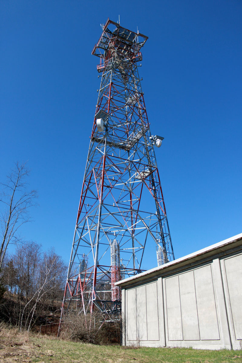
The tower is less than 200 feet tall, therefore it is no longer painted or lit. These old Western Electric towers were really built. Under that peeling paint, the galvanizing is still in near-perfect condition. The tower dates from 1968.

Former ATT tower, Rock CIty NY
Former ATT tower, Rock City, NY

The Western Electric KS-15676 microwave antennas and waveguides have been removed. The top platform is quite large, one could build a house up there. The W290BZ antenna is the cross-polarized LPA attached to the center pole which is barely visible.

Former ATT long lines site, Rock City NY.  The big empty.
Former ATT long lines site, Rock City, NY. The big empty.

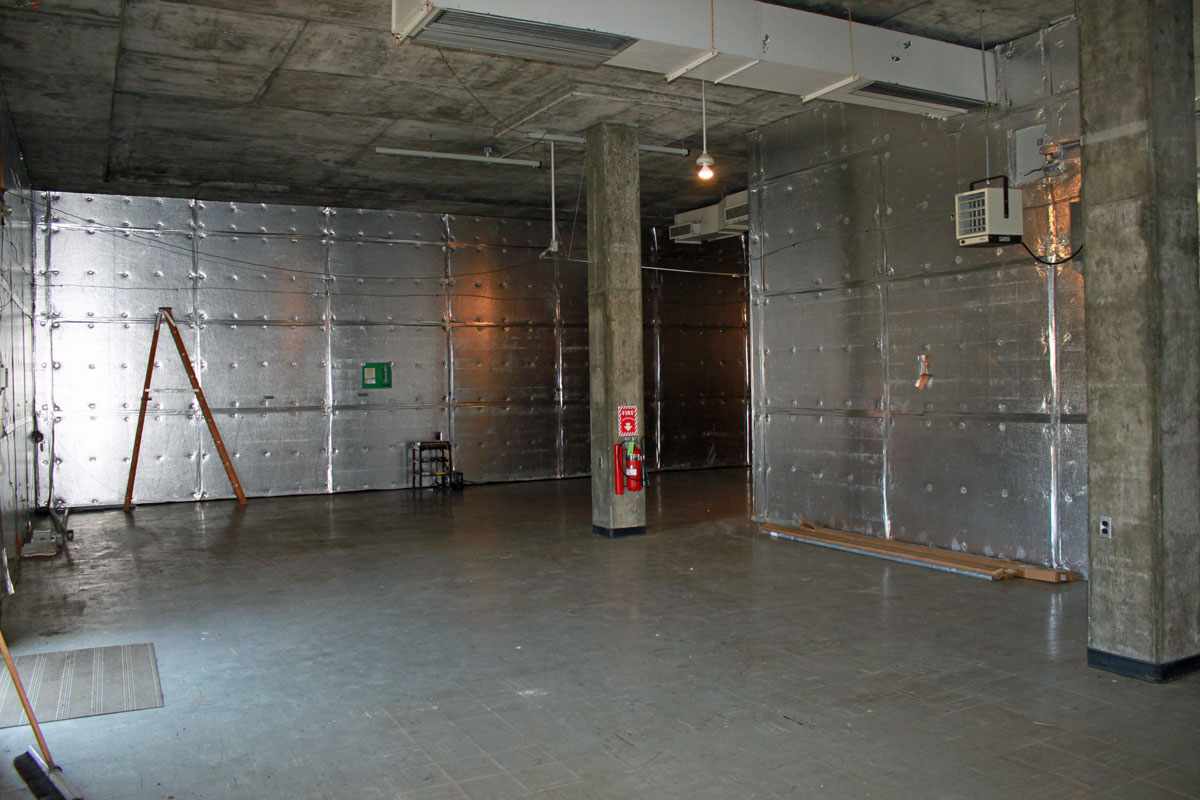
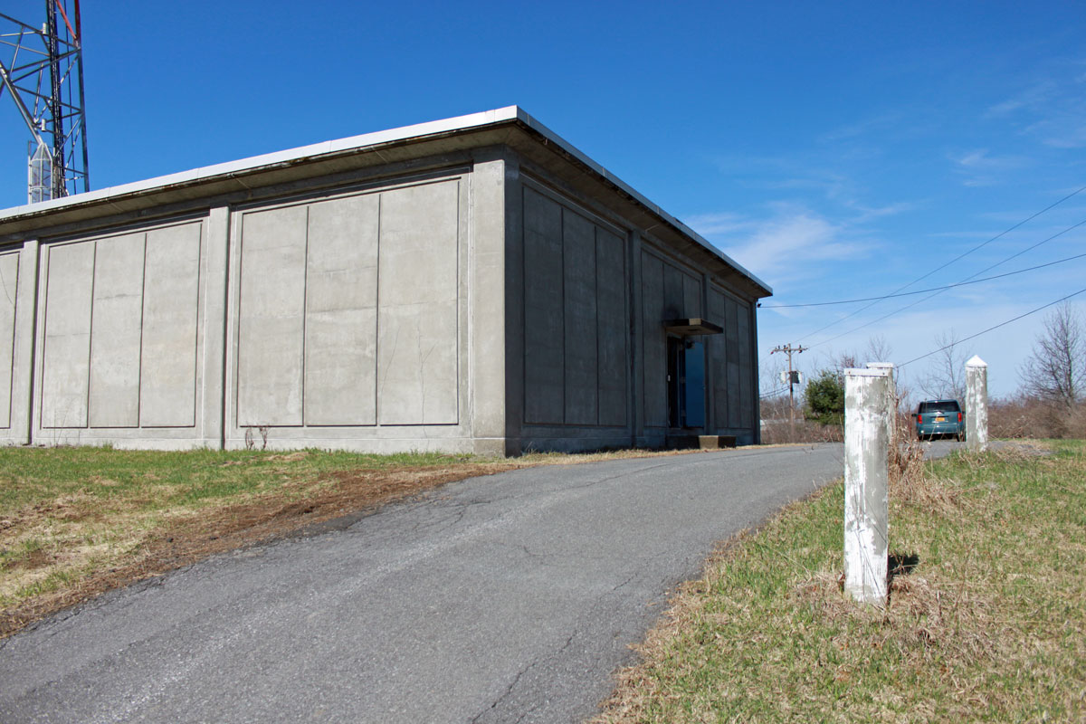
This room held the switch gear and TD-3 microwave radios.

Former ATT site, Rock City NY 100 KW generator
Former ATT site, Rock City, NY 100 KW generator

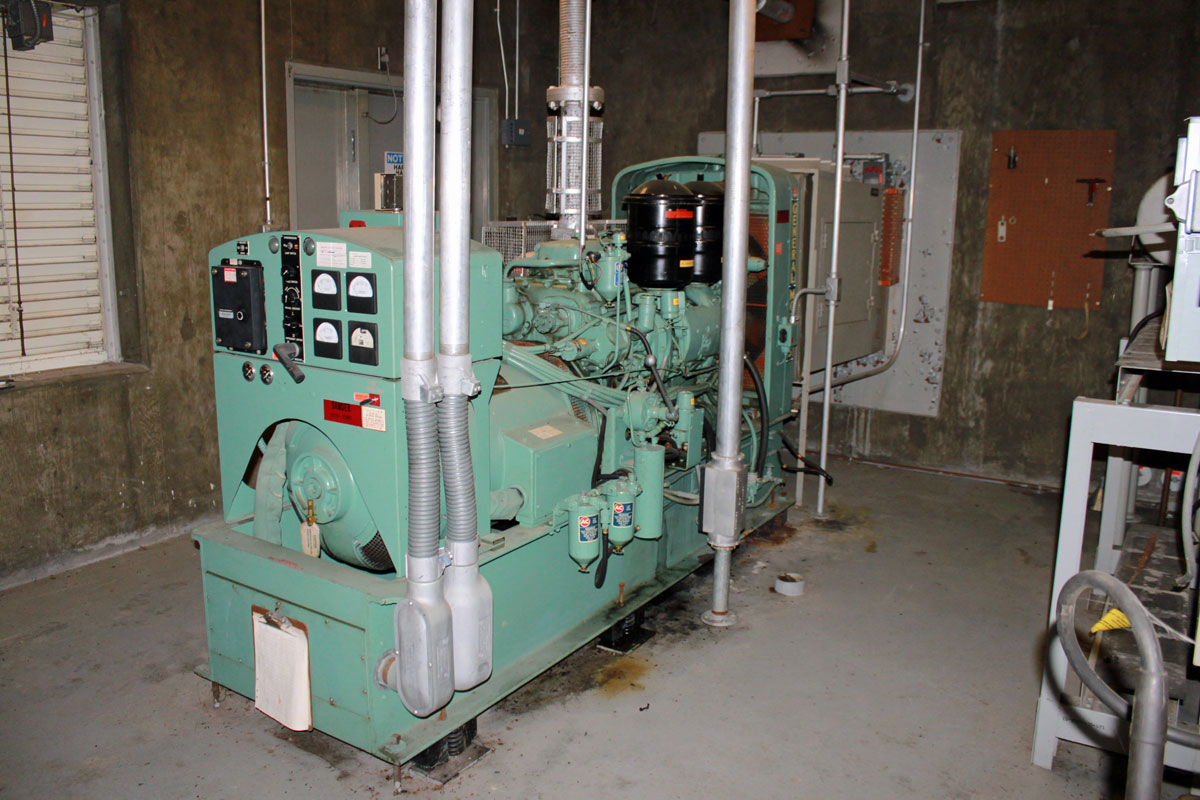
The original General Motors 100 KW diesel generator. The fuel tank was removed before the site was transferred from ATT to the new owners.  If reconnected to a fuel supply and the block heater turned on, I’d bet this unit would start and run.

ATT Rock City NY generator, Detroit Diesel straight six engine
ATT Rock City, NY generator Detroit Diesel straight six engine
ATT Rock City NY fuel tank cathodic projection unit.
ATT Rock City, NY fuel tank cathodic projection unit.

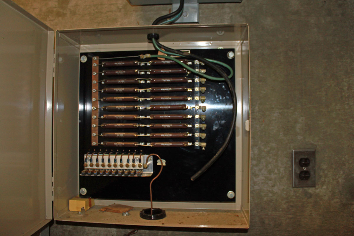
The tank had a Cathodic protection unit installed, which ran a small DC current through the tank to keep it from rusting.

The original visitor’s log book is still there, showing every ATT person who visited the site from 1968 until it was decommissioned in 1994.  This site was unmanned and remotely monitored and controlled from somewhere else.  Maintenance personnel showed up at regular intervals or to fix specific problems.

Like many of its rural counterparts, this site sits mostly empty since the microwave equipment was removed in the early 1990s.  This one seems to be well taken care of, others are in terrible shape.

Modern Art

After replacing a burned-out FM antenna for one of our clients, the question became; what do we do with the old antenna?  There were several options:

  • Throw it behind the transmitter building and let weeds and poison ivy grow over it
  • Take it to the scrap yard to get whatever money we could for it
  • Give it away to somebody
  • Turn it into a fountain

I have scrapped these old antennas before, they are made mostly of hard yellow brass, which does not net too much at the scrap yard.  In fact, by the time I finished removing the Radomes and separating the metal, I had more time for the job than it was worth for both myself and the client.  Therefore, I present to you the ERI LPX lawn fountain:

ERI LPX2E Rototiller FM antenna used as a fountain

Upon completion, my wife and daughter, who are natural-born skeptics, even had kind words to say. It seemed like a simple project at first; enlarge the dry well for the basement sump pumps and install some type of mounting base for the old antenna. It turned into a little more than that.

Mounting base for ERI antenna fountain

It took several hours of backbreaking labor, a concrete form, and a few bags of ready-mix concrete to create the mounting base. Several wheelbarrow loads of gravel, some rocks from the old wall in the woods, and a pond pump from the hardware store round out the installation.

ERI LPX2E Rototiller FM antenna fountain

I am not sure what else to say.

Troubleshooting an AM array

Today, there will be a quiz.

Recently, we had an AM antenna array go out of tolerance by a good margin.  This has been repaired, however, I thought I’d post this information and see if anybody could identify the problem and the solution. Unfortunately, I don’t have prizes to give away, however, you can show off your AM engineering prowess.

All of the information is pertinent:

  1. The station has two directional arrays (DA-2) using the same towers; the nighttime array is out of tolerance, and the daytime array is not affected and is performing normally.
  2. There were no weather events connected with this event; no electrical storms, no major temperature changes, no rain events, no freezing or thawing, etc.
  3. The problem happened all at once, one day the array was performing normally, and the next day it was not.
  4. Station management reports that some listeners were complaining that they could no longer hear the station.
  5. The ATUs and phasor were inspected; all RF contactors were in the proper position, no damaged or burned finger stock and no evidence of damaged components (inductors or capacitors) was observed.  Several mouse nests were cleaned out of the ATUs, however, this did not change the out-of-tolerance antenna readings.
  6. The towers are 1/4 wave (90 electrical degrees) tall.

Readings:

TowerPhase angle as licensedCurrent ratio as licensedPhase angle as readCurrent ratio as read
1147.20.583149.50.396
2 (reference)01.0001.00
3-1370.493-125.80.798
4107.50.48192.70.355
5-38.10.737-60.20.623
6-178.70.382142.80.305

Licensed values for common point current is 13 amps, impedance is 50 ohms j0 and there is normally no reflected power on the transmitter.  On this day, the common point current readings were 8.9 amps, impedance 38.5 ohms +j5 the transmitter had 340 watts of reflected power.

This is the overall schematic of the phasor and ATU:

WDGJ overall RF schematic diagram
WGDJ overall RF schematic diagram, click for higher resolution

Aerial view of the transmitter site, oriented north:

WGDJ aerial view showing towers as identified in schematic diagram
WGDJ aerial view showing towers as identified in the schematic diagram

So, where would you begin?  Ask questions in the comments section.