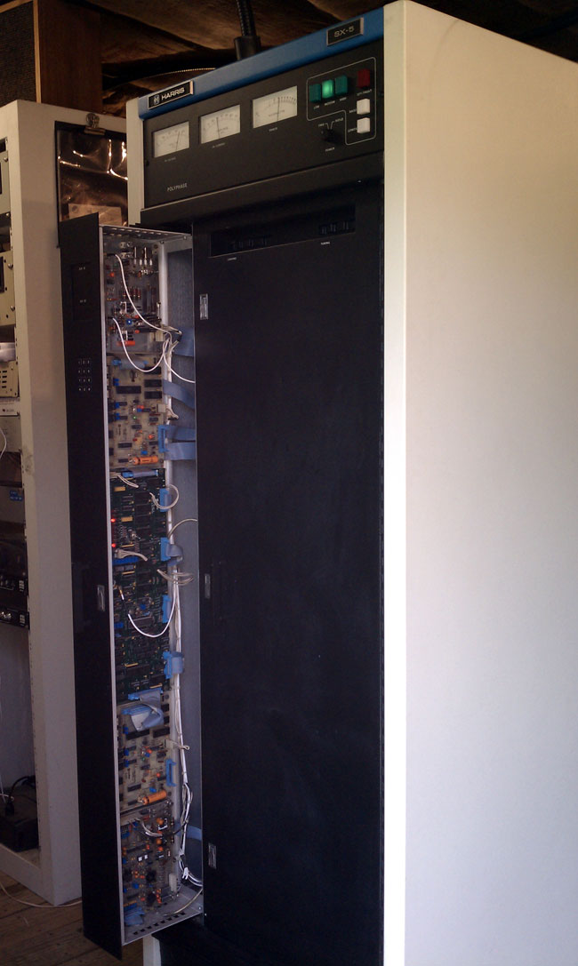
I was working on a Harris SX5 the other day and snapped a picture of the scope while measuring RF drive levels. There are still quite a few of these units out in the field, judging from my search engine results. I thought it would be helpful to post something about it. The RF power amp boards for the Harris Gates solid-state AM series transmitters are the same design, I believe.
In order to fully drive the RF MOSFETs in this particular series of transmitters (Harris SX1, 2.5, and 5 including A models) at least 26.5 volts peak to peak is required. Less than that and the device will turn full-on and internally short. To measure RF drive, the transmitter must be in local with control voltage on, with the rear door interlock defeated (this can be safely done if the transmitter is wired with separate AC feeds for control and RF power supply). Make sure the RF power supply is defeated and will not turn on. Measure across the input of each of the toroids that feed the gates of the RF devices.
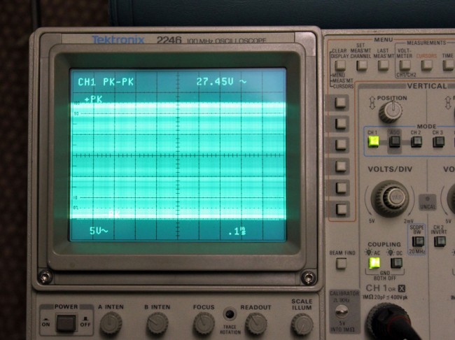
It should measure between 26.5 and 29.5 volts. This one measures 27.45 volts peak to peak. Each input toroid on every PA board should be measured as the toroids themselves have strange failure modes and may pass resistance and continuity tests, yet still not provide proper drive voltage to the attached devices. This has to do with core permeability. Each toroid feeds two RF MOSFETs, replace part is IRF-350.
As always when dealing with an SX transmitter, good luck.


We have a SX-1 as a backup..the unit will not make more than
25 watts..the raise lower controls have not effect..the control circuits function properly…
The four outputs of the PDM generator appear to be normal wave
forms at the proper levels…the input to the IPA board is 15 volts peak to peak..however the input to the PA is only 20 volts. The voltage to the PA board is around 250 volts…there is nothing in the troubleshooting section of the manual…that
deals with this problem.. the PA volts on the digital meter
reads 57…with current around .5..one PDM amp output has a
shorted Mosfet..transmitter was only doing 750 watts before the current problem…any tips would be greatly appreciated..
Sounds like insufficient drive to the PA board. Likely, all the devices on the PA board, except one or possible two, are shorted and will need to be replaced after the low drive level problem is isolated and fixed. Good luck.
Just finished up fixing a PA module on a very early SX-1. It has three 120-ohm 2W carbon-comp resistors in parallel in each drive circuit. Three of those resistor clusters had obvious signs of heat stress, and measured way lower than the expected 40-ohms…one measured 11. This was killing the drive levels, of course. Once they were replaced, the drive was at 27 V P-P on all toroid inputs, as measured with a 40+ year old HP scope…what a beast.
I also treated this transmitter to a new pair of controller batteries. It still needs the big B+ caps replaced, all of the other big blue caps have been recently shotgunned. Hopefully I can retire this box later in the year.
One other thing about this repair. While I was working on this module, I installed a loaner from a SX-1A. When I installed the loaner, I checked the MOSFETs with the Simpson 260, and found a pair blown. I replaced the parts, then did a drive-level check. On this board, there are .33uH inductors heading to the toroids…a frequency-determined part, and a convenient place to clip on the scope probe. Drive levels were perfect except for where the bad FETs were, and no .33uH inductor! In its place was an 82-ohm wirewound resistor. I don’t know if a previous engineer mistook the inductor for a resistor, or thought the wirewound resistor had enough inductance to work in the circuit. Either way, drive was only 10V P-P. Replaced with the proper inductor, and all was well.