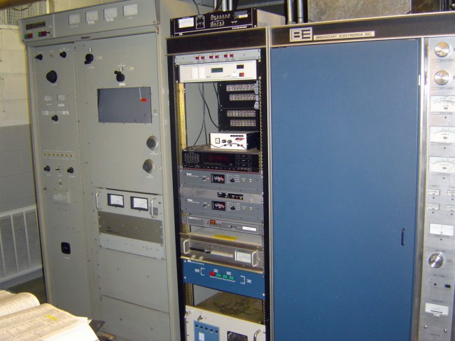
We are scrapping several old transmitters these last few weeks as part of a site upgrade A couple of Harris FM20 and 10H transmitters are out the door.
Harris FM20H transmitter, circa 1970
Some people like these transmitters. I am not one of those. I found that they were of dubious reliability, tended to drift out of tune and have AM noise problems, and had multiple catastrophic failure modes. If it was not tuned just right, it also had a tendency to have HF oscillations and internal arcing in the PA cabinet.
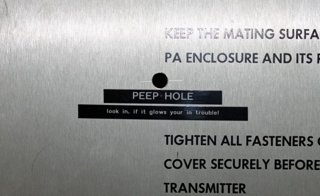
Harris FM20H3 PA cabinet modification
This transmitter had a non-factory authorized modification installed as a tuning aid. Tune for best efficiency, and minimum AM noise then check and see if it is arcing. It is also advisable to wear hearing protection during the tuning process.
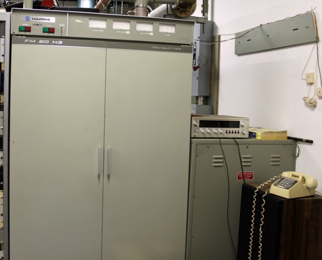
Harris FM20H3, circa 1972
This particular transmitter was my nemesis for a couple of years. It is actually possible to hate an inanimate object, I can tell you. Goodbye, you piece of shit.
We tend to scrap these instead of dumpster them. It saves the client a little bit of money on dumpster charges. If all the metal is sorted out by category, e.g. all the copper windings are cut from the HV transformer and PS filter inductors, and all the brass, aluminum, and wiring harness are separated, then it is almost worth the time and effort. Personally, I’d rather see all that material reused than landfilled.
Radio facilities, particularly mountaintop transmitter sites, are prone to power transients. The causes can be varied, but most often, lightning is the culprit. Long power transmission lines to the site are vulnerable to direct strikes and EMF-induced spikes from nearby strikes. Other issues, such as switching transients, load fluctuations, and malfunctioning equipment can lead “clear weather” outages. Of course, the best way to deal with such things is through prevention.
Power line surge suppressors have been around for quite some time. They usually take the form of a MOV (Metal Oxide Varistor) connected between the hot leg and neutral or ground. There are a few differences in designs, however. Typically, most facilities employ a parallel surge suppressor. That normally takes to form of an enclosure hung next to the main power panel with a group of MOV modules in it. The MOVs are fed from a circuit breaker in the panel. Like this:
LEA parallel or shunt surge suppressor
This is an LEA three-phase 208-volt shunt surge suppression unit, which has MOVs between all phases to ground and each other. That is connected in parallel to the electrical service with the circuit breaker disconnect. These function well enough, provided there is a good bit of series inductance before the unit and also, preferably after. The series inductance can come from many sources, including long secondary leads from the utility company transformer or electrical conductors enclosed in metal conduit, particularly rigid (verses EMT, or FMC) metal conduit. The inductance adds a bit of resistance to the transient voltages, which come in higher than 50 or 60 Hz AC waveform.
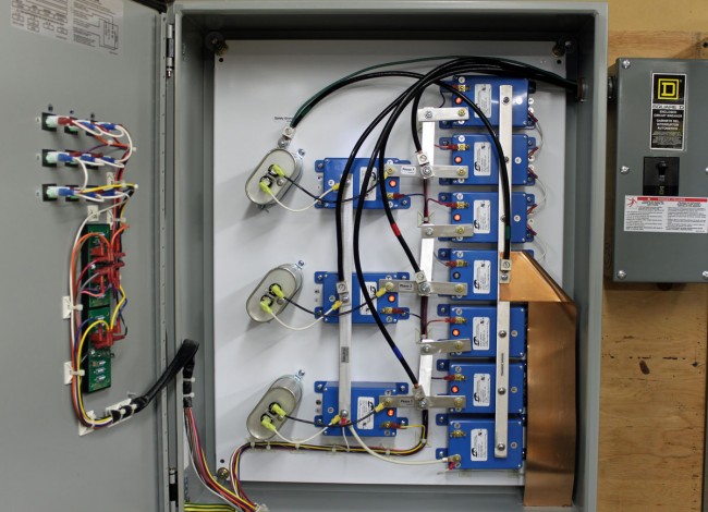
A better method of transient protection is the Series Surge Suppressor. These units are installed in line with the incoming service and include an inductor to add the required series resistance coupled with MOVs and capacitors. Most series surge suppressors also filter out harmonics and RF by design, something desirable, particularly at a transmitter site. Series surge suppressors look like this:
LEA DYNA systems series surge protector
This is an LEA three-phase 240-volt unit. As in the other example, all phases have MOVs to neutral and each other. There are MOVs and capacitors on the line and load side of this unit (the line side is the bottom of the inductor). A basic schematic looks like this:
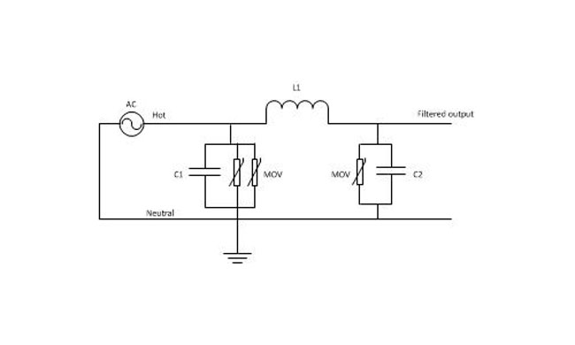
Series surge suppressor basic schematic
A few things to note; MOVs have a short circuit failure mode and must be fused to protect the incoming line from shorts to the ground. MOVs also deteriorate with age, the more they fire, the lower the breakdown voltage becomes. Eventually, they will begin to conduct current at all times and heat up, thus they should also be thermally fused. MOVs that are not properly protected from overcurrent or over-temperature conditions have the alarming capacity to explode and/or catch on fire. From experience, this is something to be avoided. Matched MOVs can be paralleled to increase current handling capacity.
The inductor is in the 100 µH range, which adds almost no inductive reactance at 60 Hz. However, it becomes more resistive as the frequency goes up. Most transients, especially lightning, happen at many times the 60 Hz fundamental frequency used in power distribution (50 Hz elsewhere unless airborne, then it may be 400 Hz).
Capacitors are in the 1-10 mF range and rated for 1 KV or greater as a safety factor. The net effect of adding capacitance is to create a low-pass filter. Hypothetically speaking, of course, playing around with the capacitance values may net a better lowpass filter. For example, at 100 uH and 5 mF, the cutoff frequency is 225 Hz, or below the fourth harmonic. Care must be taken not to affect or distort the 60 Hz waveform or all sorts of bad things will happen, especially to switching power supplies.
These units also need to have a bypass method installed. If one of the MOV modules needs to be replaced, power to the unit has to be secured. This can be done by connecting it to the AC mains before any generator transfer switch. That way, the main power can be secured and the site can run on generator power while the maintenance on the surge suppression unit is taking place.
Most radio station networks that I have seen are divided along several different lines based on functions. These functions are:
Office network; E-mail, document storage and retrieval, printing, applications like traffic and billing, promotions, music scheduling, and so on
Automation network; automation servers, workstations, and audio editing machines used in production
Audio over IP (AOIP) network; any AOIP consoles, devices, or STL equipment
Voice over IP (VOIP); telephone system
Wireless LAN; WLAN or WIFI
It is helpful, then, to segment the network into different broadcast domains to reduce the congestion on any one network. That is where a good subnetting scheme can be beneficial. Subnets segment the network into smaller parts, reducing the amount of broadcast traffic and increasing network speeds by reducing MAC table sizes, and thus switching and lookup times. They also can secure certain areas of the network from the outside or other subnets, adding a level of security. For example, it may not be a good idea for automation computers or AOIP consoles to have access to the internet. Certain functions in routers and switches can be enabled for that added security.
It is also important to efficiently use IP addresses in a large organization where WANs are used. The better the subnetting scheme, the easier it is to understand and the better it performs. Avoiding or reducing discontiguous networks is key to efficient and speedy routing. That is an important consideration where applications like AOIP and VOIP are concerned
To really understand subnetting, it must be broken down into fundamental parts. This pertains to IPv4, which will likely remain in use for quite some time. The big chart, class B networks:
3nd octet
4th octet
CIDR
Decimal
Wild card
Hosts
3rd Up by
Subnets
00000000
00000000
/16
255.255.0.0
0.0.255.255
65,534
255
0
10000000
00000000
/17
255.255.128.0
0.0.127.255
32,766
128
2
11000000
00000000
/18
255.255.192.0
0.0.63.255
16,382
64
4
11100000
00000000
/19
255.255.224.0
0.0.31.255
8,190
32
8
11110000
00000000
/20
255.255.240.0
0.0.15.255
4,094
16
16
11111000
00000000
/21
255.255.248.0
0.0.7.255
2,046
8
32
11111100
00000000
/22
255.255.252.0
0.0.3.255
1,022
4
64
11111110
00000000
/23
255.255.254.0
0.0.1.255
510
2
128
11111111
00000000
/24
255.255.255.0
0.0.0.255
254
1
256
Class C networks
3rd octet
4th octet
CIDR
Decimal
Wild card
Hosts
4th Up by
SubnetsB
SubnetsC
11111111
00000000
/24
255.255.255.0
0.0.0.255
254
255
256
0
11111111
10000000
/25
255.255.255.128
0.0.0.127
126
128
512
2
11111111
11000000
/26
255.255.255.192
0.0.0.63
62
64
1024
4
11111111
11100000
/27
255.255.255.224
0.0.0.31
30
32
2048
8
11111111
11110000
/28
255.255.255.240
0.0.0.15
14
16
4096
16
11111111
11111000
/29
255.255.255.248
0.0.0.7
6
8
8192
32
11111111
11111100
/30
255.255.255.252
0.0.0.3
2
4
16384
64
11111111
11111110
/31
255.255.255.254
0.0.0.1
0
2
N/A
11111111
11111111
/32
255.255.255.255
0.0.0.0
0
1
N/A
The terms “Class B” and “Class C” networks are outdated. Basically, I broke the chart up along a classful boundary to make it easier to read.
An IP v4 address consists of four octets of binary data. A common example is 192.168.1.154, which in binary numbers looks like this: 11000000.10101000.00000001.11111110. It is converted to base ten numbers (dotted decimal) so that we humans can deal with it. A typical subnet mask seen in many office networks is 255.255.255.0, which in binary looks like this: 11111111.11111111.11111111.00000000. When a router receives a packet, it does something called an “ANDing process.” When a router ANDs, it overlays the subnet mask on the network address and uses the following function: 1+1 = 1, 1+0 = 0 and 0+0 = 0. Thus, in the above example, a router AND would look like this:
Dotted Decimal
Binary Octets
192
168
1
254
255
255
255
0
192
168
1
0
11000000
10101000
00000001
11111110
11111111
11111111
11111111
00000000
11000000
10101000
00000001
00000000
The subnet mask is telling the router to ignore the last octet, thus saving a bit of time and processing power. It may seem very small and insignificant. When considering that routers make sometimes hundreds or thousands of routing decisions in a second, even a small bit of work reduction adds up quickly. Subnet masks allow routers to look at only the layer three network address, ignoring the host portion. This takes advantage of IPs inherent hierarchical addressing system and speeds the process of routing to the proper destination.
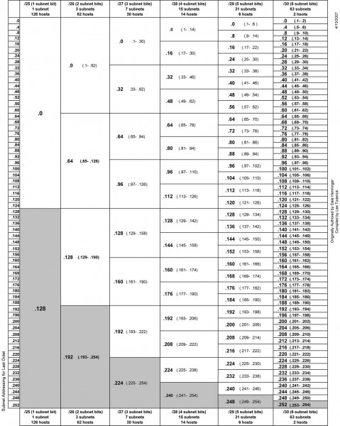
Another way to look at it:
IPv4 subnet chart, click for .pdf version
There are three IPv4 address ranges set aside for private (internal) use:
192.168.0.0 to 192.168.255.255 /16
172.16.0.0 to 172.31.255.255 /12
10.0.0.0 to 10.255.255.255 /8
Thus, very large networks can use an internal IP address scheme in the 10.0.0.0 range and have up to 16,777,216 hosts, or 224 addresses minus two, one for the network line address and one for the broadcast address. That would be one giant network clogged with ARP requests, ICMP packets and other miscellaneous multicast messages. A notation of /16 means that 16 bits are used for the network address, the remaining address bits are host bits. A /24 network has 24 network bits and 8 host bits making the available hosts 254.
An example of an efficient network would be a medium market operation with six radio station under one roof. This facility has ten studios and a newsroom using AOIP consoles, a VOIP phone system, an automation system, an office network with an internal file server and exchange server. The number of required hosts on each subnetwork is
Office network, servers and wireless hosts: 78
VOIP phone system: 70
AOIP consoles and nodes: 30
Broadcast automation system: 22
Given IP address: 172.19.0.0 /22
In most instances, office networks are usually installed on one class C segment, that is to say, the network mask is 255.255.255.0. However, in the example above, 254 hosts are not needed on the office network, thus it can be divided in half using the subnet mask of 255.255.255.128, leaving the other half for the VOIP phone system. This subnetting scheme would leave 126 hosts on the office network and 126 hosts on the VOIP network. The AOIP console and broadcast automation system can be placed on another class C segment, using the subnet mask of 255.255.255.192, which would give each subnet 62 hosts. All subnets would have room to expand. Each subnet is isolated from the others by a router. The office subnet contains the gateway to the internet, usually .1 or .126 (first or last) IP address.
That would look something like this:
Office network
Line address
First available
Last available
Broadcast
Subnet mask
172.19.0.0
172.19.0.1
172.19.0.126
172.19.0.127
255.255.255.128
VOIP phone system
Line address
First available
Last available
Broadcast
Subnet mask
172.19.0.128
172.19.0.129
172.19.0.254
172.19.0.255
255.255.255.128
AOIP consoles and nodes
Line address
First available
Last available
Broadcast
Subnet mask
172.19.1.0
172.19.1.1
172.19.1.62
172.19.1.63
255.255.255.192
Broadcast Automation system
Line address
First available
Last available
Broadcast
Subnet mask
172.19.1.64
172.19.1.65
172.19.1.126
172.19.1.127
255.255.255.192
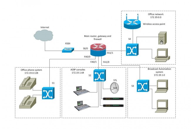
That keeps the network segments small but has room to grow. This is a diagram of a converged network:
Radio Broadcast Facility converged network
With a setup like this, reliability is the key to a happy life. The router should be a good Cisco product with four or more Fast Ethernet ports. A second way to do this would be to have four routers plugged into a distribution switch and use OSPF to route between subnetworks. The switches should also be a good Cisco product, which can take advantage of port security options and QoS on the VOIP and AOIP segments. VOIP systems usually require Power over Ethernet (POE) ports, thus that switch can be specialized for that purpose.
Many AOIP systems want to see Gigabit switches or at least Fast Ethernet switches with Gigabit or better backplanes. Any AOIP STL system can be connected to the AOIP network along with other things like AOIP remote broadcast and studio telephone solutions.
Many WLAN access points can be configured as a network router and DHCP server for wireless hosts.
The largest users of the public (i.e. internet) network would be the VOIP phone system and office network. The broadcast automation network may also be a if voice tracking or other program delivery over WAN is used.
My son and daughter are playing ice hockey this winter. This means that every Saturday morning I have to get up very early and haul them off to the rink for practice and a game. It is actually a lot of fun because I love watching them play. Having played a certain version of pond hockey in my youth, it brings back good memories.
In any case, last week, after they finished their game and changed out of their hockey gear, my son wanted to watch the older kids play. Thus, we sat down in the bleachers for a few minutes to watch the 12-15-year-olds play against a traveling team. Most hockey leagues are mixed, that is to say, girls and boys play on the same team. Not to put too fine a point on it, but the girls can be decerned not only by their ponytails but also the pink stake laces or pink hockey gloves. I also noticed that the girls seem to play a more cerebral version of the game, which is a joy to watch.
Not soon after we sat down, a fast break play developed at mid-ice. It was truly a thing of beauty. A player from the home team intercepted a pass from the opposing team and took off down the ice. She was followed closely by another player from her own team. As they crossed the opposing red line, the other team closed in. I watched the lead player move fast toward the goal and then fake out the goalie, lifting her stick oh so much as she made the shot. The goalie was completely fooled and dove for the non-existing puck, which was left on the ice for the following player, who neatly scooped it into the goal under the goalie’s leg. It was over in a flash of white jerseys and pink laces. I thought to myself; these are kids are great! You do not have to watch an NHL game to see good hockey and sometimes the so-called “professional” sports are overrated anyway.
Which got me thinking about LPFM. How many budding journalists, play-by-play announcers, DJs, and presenters are out there waiting for an opportunity to show their stuff? An opportunity that they may never get because most commercial and many public radio stations are locked into an increasing automation loop. Locally originated programming is constantly being cut and replaced by satellite-syndicated formats and or out-of-market voice tracking. It is truly a shame because the strongest leg that terrestrial radio can stand on is localism.
LPFM can be that opportunity to return the radio to its community of license. It will not be easy, clearly, the rules were written to prevent LPFM from ever competing with commercial or even public radio stations. Restrictive power levels, odious interference rules, and limited fundraising capability will keep all but true believers and perhaps ignorant souls from attempting for a license. It will be hard, but not impossible, and true believers will make a go of it. The October 15th, 2013 filing window will very likely be the last opportunity for community organizations to establish a local radio station. After that, the remaining spectrum crumbs will be divided between translator aggregators to create ever larger networks of mostly redundant content.
Terrestrial radio may well go through an evolutionary change. As more and more broadcasters are finding out, once a license is owned, there is a great deal of expense in operating a station. Things like employees and office supplies can be cut, however; towers need to be maintained, transmitters and antennas need to be replaced periodically, electricity bills must be paid, etc. The larger the station, the more operating costs are involved. Another serious economic downturn like 2008 and the crazy train will be off the rails. The inexpensive-to-operate, volunteer-run local LPFM may indeed be the last radio station(s) standing. I have heard many decry this type of station as “amateurish” or “not professional.” Here is what can happen if you give a bunch of amateurs a free hand: