UPDATE and bump: This post is from eleven years ago, but I have been working on an SDR project using one of the RTL- 2832 chips. I had to make two more of these units, so the prices and part numbers have been updated.
I have acquired one of those broad-banded software-defined radios, an Icom PCR-1000 to be precise, and all is well. I am enjoying listening to various MF, HF and VHF radio stations. However, there is a slight problem. Very slight, almost too small to even mention, more of an inconvenience than a problem. Still, if I am being inconvenienced, then others are too. This issue is with the antennas. My K9AY antenna works wonderfully from 500 KHz to 25 MHz or so. My discone antenna works wonderfully from about 30 MHz all the way up to about 1 GHz. In order to enjoy the full range of the receiver, I need to switch antennas. I have a small switch on my desktop, but it seems inconvenient to reach over and switch it when going from the AM band to the FM band or something similar. Therefore, I have decided that I need an HF/VHF receiver diplexer. One would think that such hardware is ready-made for such instances. However, nothing I could find commercially would do the trick.
Thus, since I could not buy one, I decided to build one to add to my collection of receiver doo-dads and nick knacks. The design is relatively easy, a back-to-back low pass/high pass filter system with a 50-ohm impedance throughout. Something with a sharp cut-off around 30 MHz or so:

Looks pretty good, 5th order Chebyshev filter, perhaps .1 dB ripple in the pass bands if well made. Schematically:

Then it comes down to the building. Since this is going to be used in the UHF range, care and attention needs to be paid to the layout of the components and the design of the circuit board. Some of those capacitance values are not standard, however, by using two capacitors in parallel, one can get pretty close. Since this is going to be used for receiving only, I may be splitting hairs, however, I have found that well-designed and built equipment is worth the extra effort.
The board layout looks like this:

I tried to keep the traces as close to 50 Ohm impedance as possible.
As one may be able to discern, C2 and C3 are in parallel to make 192 PF, C5 and C6 are in parallel to make 60 PF, and C7 and C8 are in parallel to make 163 PF.
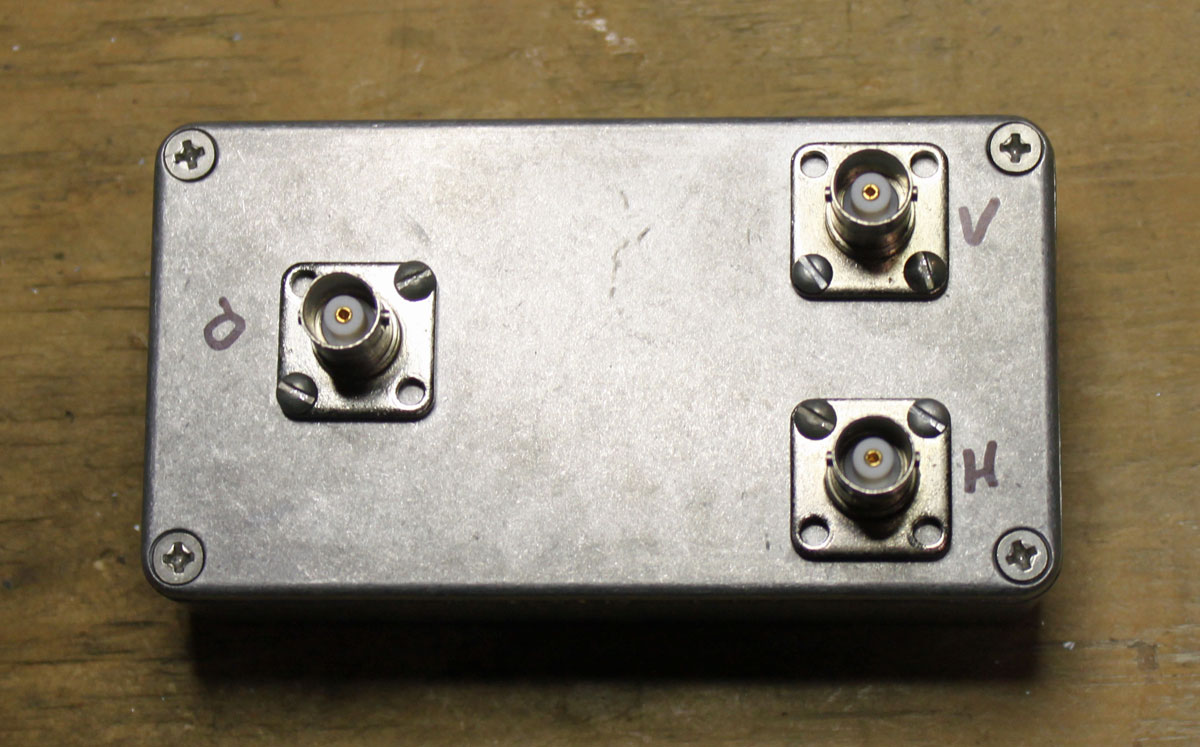
The input and output RF connectors are whatever the builder wants to use, however, I would recommend at least BNC or type N for the VHF/UHF side. My unit has all type BNC female connectors. Parts list:
| Nomenclature | Value | Mouser number | Cost (USD) |
| C1 | 150 PF SMT | 581-12065A151FAT2A | 0.72 |
| C2 | 12 PF SMT | 581-12061A120JAT2A | 0.26 |
| C3 | 180 PF SMT | 810-CGA5C4C0G2J181J | 0.27 |
| C4 | 68 PF SMT | 77-VJ1206A680FXACBC | 0.59 |
| C5 | 50 PF SMT | 581-12062A500KAT2A | 0.41 |
| C6 | 10 PF SMT | 80-C1206C100J2G | 0.54 |
| C7 | 3 PF SMT | 581-12061A3R0CAT2A | 0.34 |
| C8 | 160 PF SMT | 581-12065A161J | 0.34 |
| Case | Diecast, 4.3 x 2.3” | 546-1590WB | 10.71 |
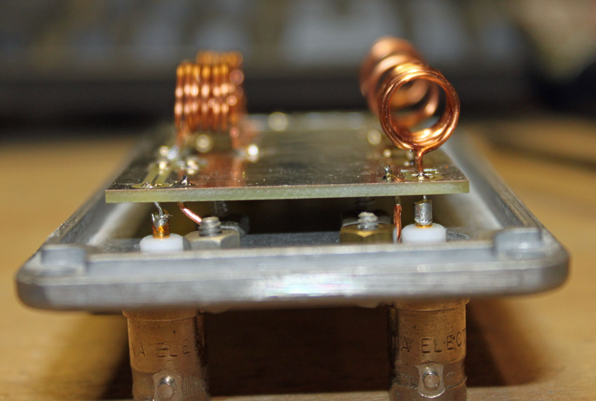
I chose a smallish, diecast aluminum case, which matches my other receiver gear. The circuit board noted above is 2.9 x 1.7 inches, which is a little bit small. I used 18 gauge wire between the input/output connectors and the board.
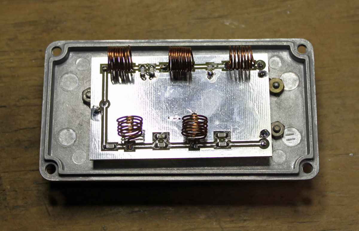
The inductors were made by hand. I used a small screwdriver as a winding form, making the turns tightly and then spreading them out to the proper distance.
Inductor chart:
| Inductor | Value (nH) | Diameter (mm) | Turns | Length (mm) |
| L1 | 173 | 8 | 6 | 9.5 |
| L2 | 468 | 8 | 10 | 9.8 |
| L3 | 414 | 8 | 9 | 8.7 |
| L4 | 146 | 8 | 5 | 7.2 |
| L5 | 186 | 8 | 6 | 8.6 |
The most expensive part was the circuit board, which cost about $16.00. The rest parts were about $22.00 including shipping.
As built photos:
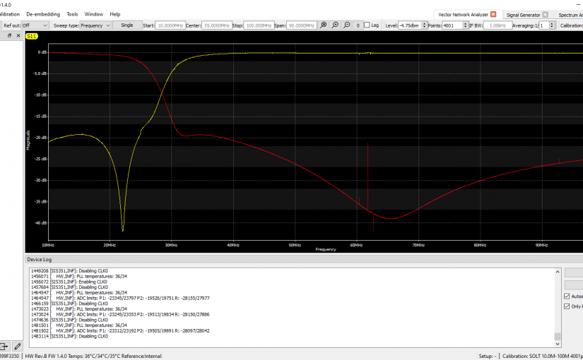
I have installed this already and it works great. I will need to get the spectrum analyzer out and run some signals through the various ports to see the attenuation and 3 dB roll-off points.


")
Both Diamond and Comet make antennas and two-way and three-way splitters/combiners good for a couple hundred watts, although not necessarily with the ranges you need. I’ve used them with 146/445 MHz radios using a dual-band antenna but they can also split one dual-band radio to use two antennas. They contain very simple HP and LP filters and some models will support 1-30 MHz on one port. Now, they may cost more than the ~$34 that yours does, but why reinvent the wheel?
Bob M.
Bob, before I started this project, I looked at the commercially available diplexers. They all seemed to exclude a major portion of the AM broadcast band, which in my view is a downside. Additionally, their designed mostly as band pass units for specific amateur frequencies, I was looking for coverage of the entire spectrum. Besides, re-inventing the wheel can be fun at times.
The VHF/UHF unit I had seems to just be a low-pass that cut off around 250 MHz, and a high-pass that started around 250 MHz. They passed everything within their respective ranges.
The triplexer that I’m currently using has ports for ~50 MHz, 146 MHz, and 445 MHz. I’m guessing that the VHF port is the only one with a definite bandpass characteristic; the other two are open from almost DC to maybe 75 MHz and from about 300 MHz and higher.
I guess you don’t really know what it passes unless you scope it out. The published specs don’t always tell the whole picture. And of course you probably couldn’t find one with a 30 MHz split like you needed.
Bob M.
Hello Paul,
Very nice design and construction, congrats!
And i’m (too…) curious, what is the software
you are using for the simulation ?
My best 73,
Rudi, HB9ARI
Hello Rudi,
The initial design was made by something called “diplexor” which came with the 2011 ARRL handbook. I did the coil dimensions by hand.
Thank you for the info. Paul
73,
Rudi
I realize this is an old post, but do you have an Eagle file or something similar that you could put up for download? I also have a PCR-1000 and I stumbled across this looking for a diplexer that would do exactly what your does.
Who made your circuit board? I’d like to order one or more from the same place.
Thank you,
73,
Ed – W8ECB
Ed, I sent that out to China and had five or six made. I may still have a few laying around, I’d be glad to sell you one if you contact me off line.
Hi Paul; Nicely done. How was the China PCB board experience for you? I’m thinking of making some interdigital bandpass filters and was considering China or Northern Industrial services.
In January I built a ham radio triplexor to split a triband beam between 20/15/10. I was too cheap to use a bud cabinet, so I used an empty 1 gallon paint can available at Lowes. Your filter would fit in the quart size can.
Rudi;
The diplexor software is included in the Elsie program; http://tonnesoftware.com/elsiedownload.html
73, K2TR
Hey Fred, I used PCB Express and they were pretty good. I think it took about three weeks, but that was before COVID. I don’t know how long it would take these days…
Have you used a NanoVNA for testing?
Something like the NanoVNA P2 Plus4 Pro.
https://nanorfe.com/nanovna-v2.html
Hi Paul –
Those China one-off PCB shops are a godsend for projects like that. It’s nice to not have to screw with hassle of the ferric chloride copper etchent anymore.
Looking at your pics, are you familiar with the ‘Manhattan’ style for circuit prototyping? I recently ordered the pads and am really liking how clean the construction can be, Dave Richard’s blog (AA7EE) turned me on to it :
https://aa7ee.wordpress.com/2011/07/24/the-wbr-a-simple-high-performance-regen-receiver-for-40m-by-n1byt/
FleaBay has the pads :
https://www.ebay.com/itm/143826734716
Hi Geoff, not familiar with the Manhattan prototyping, I will have to give that a try. Looks better than the dead bug style that I usually use. Thanks for the link to Dave Richard’s blog, looks like a good resource.
Bill, I have an older NanoVNA, V2 I think. It is okay but sometimes the screen blanks out (usually at the worst possible time), so I like using the Libra VNA better.