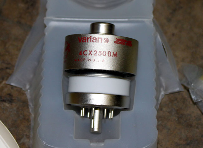
It’s a cute little thing. These were often used for driver tubes in FM broadcast transmitters. With the naming conventions of ceramic tubes, we can tell quite a bit about the unit without even looking at the datasheet.
- The first number indicates the number of grids in the tube, 3 makes it a triode, 4 tetrode, and 5 pentode.
- The C means it is a ceramic tube
- The X indicates it is air cooled, a V is vapor cooled, W is water cooled, M is multiphase
- The 250 is the plate dissipation is watts
- B is the design revision.
Thus a 4CV100,000 is a vapor-cooled tube capable of dissipating 100,000 watts, something one might find in a high-powered MF or HF transmitter.
Other bits of critical information about tubes would be maximum plate voltage, maximum screen voltage, maximum grid voltage, maximum screen dissipation, maximum grid dissipation, and filament voltage. Something to keep in mind when tuning a transmitter.
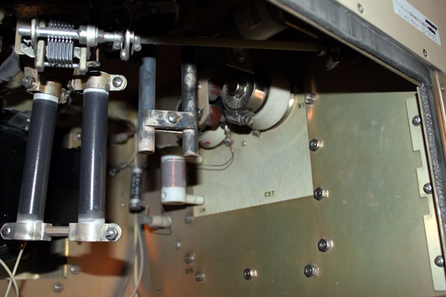
This particular tube is installed in the driver section of a Continental 816R2 transmitter.
I have noticed that these tubes have a much shorter life than there predecessors. Back ten or twenty years ago, they usually lasted 12-14 months. The latest set lasted only 8 months and both units failed catastrophically. That points to one of two things; either something in the transmitter has changed or something in the way the tubes are manufactured has changed. Once the new tubes were installed, I checked all of the parameters against previous maintenance logs. I also checked things like air flow, dirt and other possible culprits.
I could find no changes in the transmitter. The only thing I can think of is the fact that the tubes are installed horizontally, which causes the elements to warp and eventually break or short.
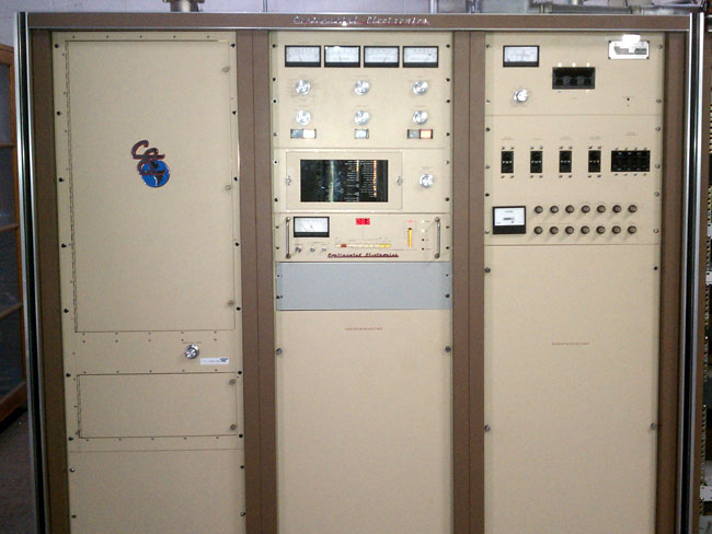
I am thinking we may try to convert the driver section of this transmitter to a solid state unit. The transmitter itself is 24 years old, but is still works and sounds great. I’d hate to get rid of it because of its driver section.


‘Gotta love that 4CX250B. In the early 70’s, Motorola used pairs of them for 275 Watt base stations in the 450-470 Mhz land mobile service. I was assigned to replace a tube IPA with a 40 Watt solid state exciter. Just as I started, the PAs began to fail in final test, making barely 180 Watts regardless of drive and input.
Eimac, which was Motorola’s sole approved source at the time, denied any change had been made to the 4CX250B despite clear evidence to the contrary; besides, they said, the 4CX250 was designed as a radar modulator and it was passing all their production tests – none of which involved UHF operation. I could find no cause in the PA, other than the use of a radar modulator tube in the first place.
Amperex had been removed from the source list long before my time because its plate capacitance wouldn’t allow tuning at the top of the land mobile band. By shortening the plate line, I was able to make the spec 275 Watts at 470 MHz with the Amperex 4CX250’s. Amperex was all too pleased to be “back on the print.” Eimac was off.
Not until Amperex had the business did Eimac suddenly remember a running change to the 4CX250’s internal cathode support. I vaguely recall they had changed the copper alloy and began nickel plating it. The plating apparently degraded the skin effect in the cathode support.
Once Eimac remembered the change, they knew how to make a special to get Motorola’s business back. It had a four letter suffix I can no longer recall. Gotta love that 4CX250.
That is interesting Dave, I think the 4CX250B has a medical application, which may be why the design was modified. I think fewer and fewer broadcasters are using tubes like this, with most transmitters having solid state driver sections. EIMAC/VARIAN/CPI needs to find new markets for their products or else they will be out of business.
I’ve seen these tubes from other places, National, Svetlana, etc, but I always have used EIMAC
Just a few weeks ago, I was called in to look at this same model/era transmitter…symptoms were erratic and unstable IPA tuning. The TPO of this station is only 14kw, so the 20kw TX should have been coasting. I did all the usual checks and found everything to be in perfect shape…finally pulled the tubes out…they looked a little different, turns out they were 4CX150A, not 4CX250B. Same size/pinout, but the 4CX150A has a glass base not ceramic (which makes me question the C designation in the model number). The station actually had a pair of brand new 4CX250B tubes on the shelf, put those in and all was well.
@Chris, the grid and screen capacitances are different between the two types. Also, the 4CX150A is also known as a 4X150 or a 7035, which was the original RCA designation. I had an RCA BTA-5J (ampliphase) transmitter that used two of those tubes as drivers for the 3CX5000 tubes. It was difficult to find units that worked right in that transmitter, Burle was the only manufacture that made a tube that worked consistently.
Hi Paul,
Long time reader, first time “commentor”. Great to see “FLY” is still using the Continental! Not to totally get off the subject of the IPA tubes, but that was one of the very first transmitters I ever saw in person, and THE first actual transmitter to go on my website. (The first transmitter was my college station’s CSI transmitter driven with a Continental exciter). Anyways, back in 1995(?) was when I took my visit of the site, driving around the mountain up there photographing towers, and noticed a car in the parking lot of that very transmitter. I initially knocked on the door, but there was no answer (the fan noise would’ve made it impossible to hear anyways), so I drove up, took other pictures, came back, and the chief engineer was standing outside. I introduced myself and he let me in to take pictures. At the time, they were on the backup Rockell Collins transmitter, and the chief (I believe his name was Roger Brace, but I may be mistaken) was working to “restore” things after a lightning strike. While there he switched back over to the Continental, which, as a young college student thoroughly interested in Broadcast Engineering, I thought was the coolest thing I had seen. There used to be a LPTV in that building too.
Paul, I have really enjoyed your blog, learned quite a bit, and very thoroughly enjoyed the pictures too.
Pretty interesting to see stations I grew up listening to in the Berkshires’ transmitters.
Take care, and keep up the great work.
— Mike Fitzpatrick
http://www.necrat.us Webmaster
Engineer: WPRI-TV/WNAC-TV
Providence, RI.
Hi Mike,
That is interesting. I worked at FLY from 91-94, in 95 I was across town at WGY/WRVE. The Collins transmitter (831D2) is still there as a backup, as is the LPTV.
I’ve stopped by NECRAT several times over the years and enjoy all the pictures of various transmitter sites around the country. If you ever need anything, let me know.
well the 4cx250B dosnt like much over 10 watts Gride drive eather and Ive seen lots tube boxes at some of the station some of witch are use exciters with more over 20 watts not cut back to ten watts I think this is short life the tubes to and I have a station I’ve been working on a Z6HD exciter that was blowing the main output amp 10 amp fuse ever two three weeks we paid Harris to fix it but it was still doing that it might be that fuse need to brought up to a fifteen amp and we paid all that money for nothing
Maybe I’m being naive here- I’m a TV satellite truck operator and maintenance technician, not a transmitter engineer- but couldn’t the tube be reoriented to sit vertically? I can’t tell exactly what is in the cabinet from the picture, but I would think that some sort of L shaped bracket could be used to hold the socket. Perhaps the tuning mechanism I see in the photo would prevent that; like I said I’m not really a transmitter engineer.
@valvashon, the picture of the tubes installed in the transmitter is looking up from the access door at the side of the PA tube input section. It would be very hard to move that section to a vertical mounting. A better idea would be to replace them with the solid state driver upgrade available from Continental.
Thanks for the clarification. Just out of curiosity, what is the cost of the tube vs. the solid state replacement? Using the solid state driver seems like an obvious choice, but then I’m not paying the bills at a small FM station.
At the time this transmitter was made (1988), tubes were cheaper and far more reliable than solid state devices for these frequencies and power levels. Nowadays, solid state would be the way to go on anything except perhaps the highest power transmitters, above 20 KW. Even then, some manufactures have come out with excellent high power solid state VHF transmitters.
The conduction cooled version is the 8560A. I’ve seen a Motorola Repeater with a manufacture date in March of 1964 that used them as well. I spoke with an older engineer who told me that, if the PA is tuned properly, it will continue transmitting for another 25 years. I believe he said the coupling had to be pretty loose on it.
Kris, you tripped the spam alarm.
A few comments. Not sure how I stumbled onto your website, probably Googled 8560A since I was working on something with one in it. BTW the photo of your 4CX250BM needs an explanation. In rare instances a letter was added to the type designation by Eimac for special purposes that were not defined in the normal scheme. The tube shown is an example of that, 4CX250BM is a tube made to meet Marconi specifications for a military radio transmitter. Hence a 4CX250B-Marconi! That tube is more costly than a regular 4CX250B because of additional testing but due to surplus finding its way onto the market probably explain how it came to be in your hands but there is another little known reason 4CX250BM were sold into broadcast market, specifically because that tube was excluded from an agreement between Eimac and Richardson Electronics and therefore a certain small-town tube dealer was buying them to skirt the need to buy Eimac 4CX250B tubes from Richardson at inflated prices.
By way of introduction, I was applications engineer for Eimac for 27 years until 2012 when CPI elected to eliminate that position and sent me packing. So, I have some “inside info” regarding the 4CX250B and can explain why new tubes do not provide the life that older 4CX250B’s used to give. Incidentally I get around 3 to 5 years life on old 4CX250B’;s in a GE 250W FM repeater. But (bingo!) you were correct when you said something in the way tubes are being manufactured might be involved.
BTW, a 4CX250B can operate horizontally with absolutely no problem so we can rule that out.
As I informed Mark Persons (mwpersons.com) at a NAB show, I believe it was 2010 when he came up to me at the Eimac booth to discuss short tube life and I confirmed what he had challenged me with namely that “since 2006 changes in manufacturing of 4CX250B has occurred and as a result shorter tube life is the norm” and to which I responded that “nothing can or will be done to change that at Eimac”.
The reason for changes made in the tube were twofold, one was the result of circumstances that occurred after moving the manufacturing from San Carlos to Palo Alto and something I hesitate to describe here because I am working on a book that will cover this and other facts and stories. I am debating calling it “The Downfall of Eimac as a US Manufacturer” or some such thing, it will deal with the unseen (dark) side of things that occurred after Varian took control over the Eimac division.
The other change to oxide-cathode tubes is a bit more complex so I will work on that subject at another time.
cheers, Reid Brandon W6MTF
I was responsible for installing that transmitter at WFLY around 1986. It coincided with a modest power increase from 8 to 11kW ERP that the Collins was not rated to handle. We were also running through final tubes in the Collins about every 6 or 8 months despite rigorous filament voltage management and careful tuning. The Collins was demoted to backup service and at the same time we decommissioned the original 1947 vintage GE BT-3A, for which the exotic final tubes had long become unobtainable.
Reid, interesting comment. I had no idea that the “M” stood for Marconi. I think these had been on the shelf as spares for a couple of years before we used them. Also, let me know when you finish your book, I’d like to get my hands on a copy 😉
I use a 4CX250K. The K uses a coaxial socket in a modified military surplus AM1178 cavity amplifier. Makes a great
250 w TV transmitter for 70cm.
Jim, what brand of finals were you using in the Collins? must have been something wrong, life should have been better, maybe not on the IPA tubes though. So they put the GE out to rest? Compare that to KPFA 94.1FM Berkeley where they really believe in keeping old equipment! The 1949 GE that was in service there for decades was converted to use 4CX5000A’s when the old glass tubes became hard to find, extinct might be a better word. The FCC approved of the mod but after noting the glass window in the PA let a substantial amount of rf out even with brass screening behind it, the field inspector requested a warning sign be posted that said one must limit exposure in front of the transmitter to less than X minutes was necessary (I think it is 2 minutes) – no comment on the fine engineering work that went into fitting Eimac tubes in and making them work while meeting harmonic requirements, etc., anyway it got the OK to operate and still serves as a backup to the Collins which is now a backup for a Nautel main. I wonder how many stations have three transmitters in line?
Reid
Reid – If you’re counting AM stations, WINR has three serviceable transmitters. The main is a BE AM6A, the backup is a Harris MW 5A, and the backup-backup is an RCA BTA-1R2. The RCA does have to be connected to the antenna manually, though.
Reid, IIRC, the Collins was being operated at or slightly over its maximum output rating. The new Continental we installed was a 10kW rig which provided much more margin, and loafed along. The final tubes in the Collins were Eimac, but mostly Econco rebuilds. We had a half dozen or so tubes that would be rotated in, and then sent out for rebuild. I think the tube type was a 4CX2500, but don’t quote me on that as the details are all 30-years old. The 1940’s GE transmitter was two identical cabinets joined by a short middle section. The first cabinet was a complete 250 watt transmitter functioning as an IPA which included the famous Phasitron exciter. The second cabinet was a 3kW amplifier with two finals in push-pull which had no harmonic filter because of the even order cancellation inherent with push-pull. There was an identical and mostly complete GE in storage which was obtained from another station as a source of spare parts. There were once lots of GE FM transmitters in New York State, including at all the old Rural Radio Network stations. The GE was a fun rig to operate. We donated both GE transmitters to a man in the Syracuse area who collected vintage rigs.
WFHR-FM (Wisconsin Rapids WI) had a GE FM feeding an RCA Pylon antenna back in the late 1940’s.
The GE FM was replaced by a Collins 830, which was replaced by a Harris HT20, in turn replaced by a BE.
All are still operational except the GE which was dumpstered years ago.
Until 1983 I was responsible for a GE TV transmitter for WNYT on channel 13. The modulated stage was a 4X150, but the tube drifted the video linearity as the tube aged. I tried a 4CX250B and it did only slightly better. Next was a 4CX250R. It not only eliminated the drift, but the tube lasted for years instead of 6-8 months. I’d be curious if the 4CX250R still has better life than the 4CX250B.
I will have to take notes on the GE thats still in line at KPFA. Fred, the 4X150A has lower output capacitance and has to be used in some UHF applications, such as the GE television transmitters that used it for a driver to the Klystron.
About 20 years ago there a GE UHF TV still operating in Fresno, CA but I am sure it went to the scrapper when digital came along. I was told the IPA tubes lasted many years, after all the PA only needed 50W peak sync but the engineer said the old power supplies needed lots of work to keep capacitors etc from failing, thats to be expected in 35+ yo equipment!
The military used a lot of 4X150A’s and they show up surplus some folks think they are rated for less output but they’ll work the same as a 4CX250B at lower freqs as long as you cool the anode so the glass doesn’t melt.
As to your experience with a long life 4CX250R, there’s probably no explanation other than the tube you got was a good one and not operated too close to max. power. The “R” version has a slightly longer cathode spray and gives higher gain as well as a stronger mechanical grid mount (R for ruggedized). I tried a “R” in my GE VHF 250W repeater amp and it was unstable, probably neut was out but lots of folks have found the “R” will provide more output for the same drive in other equipment. I wouldn’t recommend using a 4CX250R unless the price was cheap.
The trick to getting long life on the small oxide cathode tubes is to reduce heater voltage to a value that will still provide the plate current needed for a given application. Starting this procedure on a new tube will double or possibly triple the life of a tube over running at 6V. And some still think the heater voltage on the 4CX250B is 6.3 V which is an error. CPI’s website still shows the 8560A as a 6.3V heater which it is not, that tube is a conduction cooled 4CX250B used in Motorola tube equipment (Micor repeaters). At UHF the heater voltage is reduced even further to compensate for cathode backheating.
In most cases the heater on a 4CX250B can be set to 5.8V with no problem as long as the supply voltage is well regulated, if not then one would be better off not reducing the heater voltage. Or get a regulator. Or convert to SS.
Also, if your transmitter has its driver tube(s) heater supplied from the same AC power and this common source is adjustable for the PA, then you would want to reconfigure the drivers to have a separate power source to make the heater voltage independent from the PA filament voltage. I will check and advise if the 816-xx transmitters fall into this category, I seem to recall Ken Branton, ex-field service engineer at CEC informed me of that situation.
Lastly, there is the 4CX250BC and it is touted as a premium or long life version of the “B”. It is simply a 4CX250B with a few additional turns on the heater coil to reduce cathode temperature and that tube should never have its heater voltage reduced like I described above, else the cathode temp will be too low to provide the reserve of electrons in the space charge and when called on to deliver current the cathode will begin to be the source of electrons, not the space charge and sparking will occur from the oxide/nickel interface and that leads to a evolution of gas at those locations and that will cause an internal flashover and cathode damage. That said, don’t be afraid of a 5% reduction in heater voltage its safe and well away from being too low as long as the line voltage is stable within say +/- 5% of nominal.
The GE transmitter I’ve worked has (from the factory) a Sola CV transformer for the heater voltage, a nice thing to have if your transmitter is out in the sticks like those in the country where a lot of pumps come on during irrigation in the growing season (such as in MO where they can see a 15% drop) or at the top of a mountain that has a ski lift running in the winter (another 15% scenario), or the elevator room atop an old building with 1930 wiring (ref: WBRU Brown Univ.) is that where they got the term “brown-out” 🙂
Reid has it right. Read the Eimac Data Sheet ( 1960 ) re. fil voltage 6.0 nominal +/- 5% for optimum tube life.
NB. in higher freq and some instances of higher power operation Eimac says reduce the fil voltage below 6.0.
What was the spec’d line voltage when your xmtr was made ? Odds are it wasn’t 125-127 v/ but was 110-115.
The nickel substitution story is now getting more generally recognized.
“Oh we didn’t do nuttin”.
Info needed on Eimac y-508 conduction cooled variant of the 4CX250 ??
thank you
Bob, KE6F
After reading about some of the problems of the 4cx250 tubes I am wondering if I should build an amateur amplifier in class AB1 with this type of tube. Ebay has many copies at reasonable prices and I have a surplus of tube sockets but with passing time the GI-7B tube is looking more attractive.
Trying to locate operating temperature (blower exhaust air temp) for an ongoing build.
Neil n2eye, NYC
Neil, According to the Penta Labs data sheet, maximum seal and anode temperature is 250 C, required air flow at maximum dissipation 6.5 CFM