Generators and mice

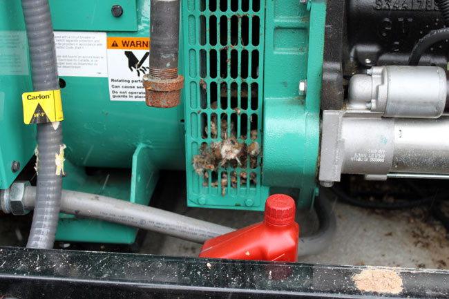
Never a good mix, unfortunately, it usually turns out bad for the mice and sometimes the equipment.  This is an Onan GGMA 20 KW propane generator installed in a rural area, not that the location matters that much.  Mice will find what they perceive as a safe secure spot to hold up for the winter.

Onan GGMA20 propane generator

Unfortunately, the mice decided that the generator cooling fan was a good place to make a nest.  It probably was until the generator started, then the mice had a quick lesson in centripetal force.

Mice and generator
Mice and generator

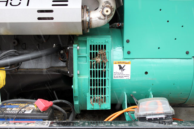
This will require some additional maintenance in the springtime when I change to oil.  By that time, the carcasses should be mostly dried out and easier to deal with.

Onan generator mice
Onan generator mice

The mice are generally a nuisance, getting into ATU’s, transmitters, electrical panels, spare parts boxes, etc.  Once in place, they begin to breed and reproduce.  The gestational period for a mouse is 21 days, which means populations rapidly increase creating further problems. If left alone, mice will chew through electrical insulation, control wires, cardboard boxes, packing material, and so on.  They tend to carry diseases like hantavirus and bubonic plague.

I don’t usually agree to using poison to get rid of pests, it tends to linger in the environment and accumulate up the food chain.  However, judicious use of some type of poison is usually the only way to effectively get rid of a mouse infestation.

Wherever possible, make sure that all openings and holes into equipment and buildings are sealed up.  Do not kill snakes and other predators, who will assist in keeping the mice in check.  Employ traps and wear gloves when removing dead mice and mouse parts.  Beware of fleas.

WNAW North Adams

Originally signed on as WMNB in 1947, it is a Class C AM station on 1230 KHz, one of thousands in the country. Initially, it had a power of 250 watts, upgrading at various times to its current power of 1,000 watts.

WNAW-WUPE-FM, North Adams, Ma circa 2012

What is different about this station is the studio building. It is located in its original place on Curran Highway on the south side of North Adams. The studio is a late Art Deco design, complete with a small glass atrium in the lobby.  Like many older radio stations, this installation was built on a raised floor.  The walls and doors are all well constructed for maximum sound attenuation.  The doors are large, heavy, and solid wood.

WNAW news room, formerly the performance studio
WNAW newsroom, formerly the performance studio

Inside, the original studios are laid out with a control room, a broadcast studio and a live performance room.  At one time, the live performance room had a grand piano.  Several times per week, live music shows were broadcast on the station.  There was a large newsroom, and a big corner office for the General Manager and sales managers.

WNAW studio monitor speakers

WNAW studio, looking into the control room.  Back in the day, the announcer, whose only concern was announcing, worked in a separate studio from the engineer on duty, who worked console in the control room.  The audio level limiting consisted of turning down the level on the console if the announcer started speaking loudly.  They often communicated with each other with hand signs through the windows.

WNAW lobby
WNAW lobby

At the time that WMNB was signed on, the Adams/North Adams Massachusetts area was in the heart of the northeast manufacturing belt.  Sprauge had a capacitor plant in Adams, GE was making plastics in Pittsfield, There were many textile mills still in operation and so on.  The population was predominantly working middle class.

WNAW control room console

Obviously, the console has been changed since those days.  The current console is a Audio Arts R-60.  This serves as the control room for WNAW and WUPE-FM.  The programming for WUPE-FM comes from Pittsfield on a T-1 line.  From here, it is relayed to the transmitter site on a 950 MHz STL.   WNAW transmitter is located about 2/10 of a mile south of the studio building on Curran Highway.  It consists of a skirted self supporting tower with a Gates 1 solid state transmitter.

WNAW-WUPE-FM equipment racks

Equipment racks containing the T-1 equipment, modulation monitors and STLs.  Note the very old Moseley TRC-15 remote controls.  We have been unwiring these at the transmitter sites and disconnecting the TELCO lines.  The transmitter sites now have Sine Systems dial up remote controls.

In 1961, WMNB-FM (now WUPE-FM) signed on the air from a tower north east of downtown, off of Mohawk Trail (MA route 2).  It broadcast on 100.1 MHz with an ERP of 1,000 watts using a Gates FM1B transmitter.

WNAW continues on today as a community based radio station and is well liked and supported.

The Harris Z6HD transmitter

These transmitters are good.   They seem to behave in a mostly normal manner, having a few quirks now and then. This particular unit is installed at WFAS-FM in White Plains NY.

Harrsi Z6HD transmitter, WFAS-FM, White Plains, NY

I believe the reason for the installation was for the HD Radio® that was in it.  The Deathstar HD Radio® exciter is in the next rack over.  No further comment is needed.

On this day, the transmitter had given up, throwing a main fan fault.  The fan (blower) motor had been replaced in the last six months (on a transmitter that is only five years old), so it was not that.  As it turns out, the stock fuses; 10 amp, slow blow, were just a little bit underrated for the job.  Harris released a service bulletin a few years ago calling for 15 amp slow blow fuses as replacements.  In any case, it was an easy fix and now there is a box of 15 amp slow blow fuses in the transmitter next to the fuse holders.

Harris Z6HD transmitter front RF modules

The modules are accessible by the front and rear of the transmitter.  These doors can be opened with the unit on the air since all of the high voltage is in the bottom of the transmitter where the blower is located.

The module in the middle is the IPA.  Each module has two RF amps, and each RF amp has two devices (BLF-177).  The devices are field replaceable, however, on the HD models, one has to make sure that the amplifiers are still linear.  On the non-HD models (Z6CD), this is not a problem at all.  Shorted MOSFETS will be noted by a fault of one entire power supply.  Removing the bad RF module will allow the transmitter to run at somewhat reduced power.  Finding the bad module may take a bit of trial and error.

Harris Z6HD transmitter back

The back of the transmitter has the directional coupler, low pass filter, access to the back of the analog exciter, controller, and remote control connection points.

The power supply at the bottom of the transmitter has multiple taps, each one with its own fuse.  These can be a bit of a chore to work on.  There is also a ribbon cable that goes from the controller to the power supply board.  This is directly in the path of the cooling fan and can flop around causing the conductors in the cable to break.  The result is the power supply may not come on or may show an unbalanced power supply condition (in the case of a three-phase transmitter).  Very difficult to diagnose.

Harris Z6HD transmitter, on air, WFAS-FM, White Plains, NY

Here it is, running again.

Lightning season

Here in the northeast, there are seasonal variations in the types of weather phenomena encountered.  Blizzards in the winter, severe thunderstorms, and the occasional tornado in the summer, at least that is the way it normally happens.  This year, we have already had two thunderstorms and a stretch of unusually warm weather.  My highly advanced personal weather prognostication technique consists of looking at trends, and the trend thus far this year is warmer with more storms.

Weather Radar, thunderstorm line

When the weather RADAR looks like this, it is too late.

To that end, it is time to go around and check all of the grounding and lightning suppression methods at various transmitter sites and studios.  I would rather spend a few minutes extra now than get called out in the middle of the night for an off-air emergency related to a lightning strike.

Proper grounding of all equipment, RF cables, and electrical service entrances is the minimum standard for transmitter sites.  Proper grounding means a common point grounding system connected to one ground potential.

To that end, all coaxial cables that enter the building need to have their outer shields bonded to the site grounding system at the base of the tower and the entrance of the building.  With an FM station where the antenna is mounted at the top of a tall tower, the coaxial cable outer jacket acts as an insulator along the length of the tower.  A lightning strike on the tower will induce a very high potential on the outer conductor of an ungrounded transmission line.  After entering the building, the lightning surge will find the next path to ground, which will likely be a coax switch or the transmitter cabinet.  Neither of those two outcomes is desired.

Thus, it was time to ground the transmission lines at WRKI, the FM transmitter we moved last January.

3 inch coaxial cable grounding kit

Fortunately, Andrew, Cablewave, Dielectric, and others make grounding kits for various size coaxial cables. They are very easy to apply and make a solid connection between the outer conductor and the site ground.

3 inch coaxial cable grounding kit

The kit contains a copper band bonded to a ground wire, stainless steel clamp, waterproofing, tape, and a pair of bolts.

3 inch coaxial cable properly grounded

The concept of transmitter site grounding is pretty simple and inexpensive to implement.  Thus, it is surprising to me how many transmitter sites, especially older sites, do not have adequate grounding.  That is an accident waiting to happen.

For more on transmitter site grounding, check Nautel’s publication (.pdf) “Recommendations for Transmitter Site Preparation.”