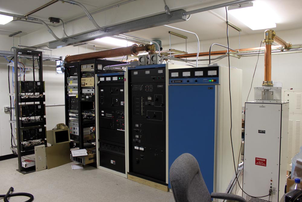
Man, this is taking longer than I thought it would. We moved the Harris FM25K last week, all went well. The only hangup, as you can see, is the harmonic filter and the height of the racks next to the transmitter. The transmitter had to go on a 4×4 to get the filter up over the racks. The output from the transmitter to the harmonic filter cannot be changed in any way, shape, or form (e.g. adding a little bit of line section to the top of the transmitter), or else the transmitter will not run. So, up on 4×4’s it is.
There we were, all ready to turn the transmitter on. Press the high voltage on button, lots of volts but no current and no power output. Seems something is wrong with the outboard IPA driver (over in the bottom of the rack, that thing pulled out with the manual on it).
The IPA is a Silicon Valley Power Amplifier 500-watt unit, which replaced the internal IPA driver about ten years ago. The tube in the Harris FM25K needs at least 390 watts to drive the transmitter to full power. Unfortunately, this particular amplifier was not in the best environment prior to the recent move. It was sitting in an unconditioned building on top of the backup transmitter in high heat and humidity. According to the manufacturer, such abuse is bound to take its toll sooner or later. The latter being, of course, the night we want to turn the thing back on and go home.
Time to drop back and punt. I found an old RVR 250-watt amp at a sister station nearby, which was also in pretty bad shape but repairable. That unit was pressed into service temporarily and with 200 watts drive, the old 25K put out about 11 KW. We need to affect permanent repairs to the RVR power amp before we place it into temporary service. I don’t want any 2 am phone calls. The Silicon Valley Power Amp needs to have the amplifier module sent back to the manufacturer and rebuilt. They will refurbish the entire thing for something like $900.00 plus shipping. Considering what it does, that is worth it.
This is a little short cellphone video of the turn-on at half power. This is a very loud transmitter, as such, I think the audio is a little distorted.
When this beast gets up to full power, I will update this, again.


Very nice clean install Paul you do great work. The transmitter move was long overdue for WINE/WRKI. That Harris 25 K has many many hours on it has served the station well and continues to run. The TFT Reciter was always trouble would like to drift. Maybe it will be better now that it is in the new building. Nice to see Pete there to push the button. I know he was the chief there few years ago. Is he back as chief? Next time you see him tell him I said hello.
@Ed, Pete says Hi. We are running into various little problems, the reciter being one of them. The 25K is on the air now, at 60 percent power while we wait for the repair of the Silicon Valley Power Amp. Otherwise, it is nearly completed.
Engineer humor: TFT= Trouble From Taiwan or Toys For Tots. Dealt with a Reciter, mine loved to drift like mad. Good luck on that one.
Kent, there is another mnemonic for TFT which I may have uttered from time to time… The reciter is fine now, we had to get a new crystal and rebuild the PLL section of the oscillated modulator, now it is stable.
What I’ve done in the past is transpose the location of the hardline and the directional coupler to get the clearance I needed, or in some cases, make a short section of hardline with field flanges to move the elbow to a point in the line where all is well. The key is to make sure that the electrical distance between the input of the filter and the output of the matching network stays the same, otherwise you can wind up with a reflection (voltage node) that can upset the balance in the PA or its neutralization. This can also upset the calibration of the power meter, but they are generally only for reference, and a calibrated downstream power meter at the output of the filter should be used for station power measurement.