WRKI WINE transmitter move, update 2

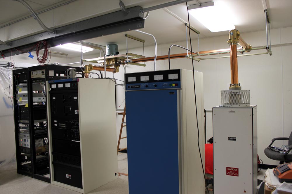
Man, this is taking longer than I thought it would. We moved the Harris FM25K last week, all went well. The only hangup, as you can see, is the harmonic filter and the height of the racks next to the transmitter. The transmitter had to go on a 4×4 to get the filter up over the racks. The output from the transmitter to the harmonic filter cannot be changed in any way, shape, or form (e.g. adding a little bit of line section to the top of the transmitter), or else the transmitter will not run. So, up on 4×4’s it is.

WRKI WINE transmitter room

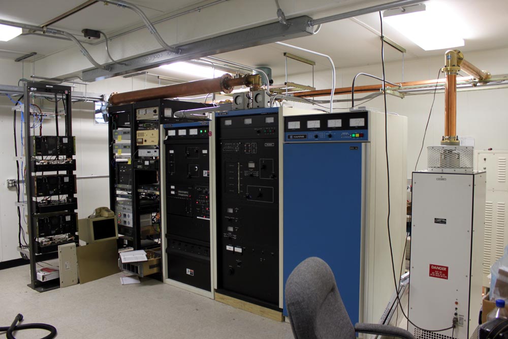
There we were, all ready to turn the transmitter on.  Press the high voltage on button, lots of volts but no current and no power output.  Seems something is wrong with the outboard IPA driver (over in the bottom of the rack, that thing pulled out with the manual on it).

The IPA is a Silicon Valley Power Amplifier 500-watt unit, which replaced the internal IPA driver about ten years ago.  The tube in the Harris FM25K needs at least 390 watts to drive the transmitter to full power.  Unfortunately, this particular amplifier was not in the best environment prior to the recent move.  It was sitting in an unconditioned building on top of the backup transmitter in high heat and humidity.  According to the manufacturer, such abuse is bound to take its toll sooner or later. The latter being, of course, the night we want to turn the thing back on and go home.

Time to drop back and punt.  I found an old RVR 250-watt amp at a sister station nearby, which was also in pretty bad shape but repairable.  That unit was pressed into service temporarily and with 200 watts drive, the old 25K put out about 11 KW.  We need to affect permanent repairs to the RVR power amp before we place it into temporary service.  I don’t want any 2 am phone calls.  The Silicon Valley Power Amp needs to have the amplifier module sent back to the manufacturer and rebuilt.  They will refurbish the entire thing for something like $900.00 plus shipping.  Considering what it does, that is worth it.

This is a little short cellphone video of the turn-on at half power.  This is a very loud transmitter, as such, I think the audio is a little distorted.

When this beast gets up to full power, I will update this, again.

Low Pass Filter design

Every good transmitter, tube transmitters, in particular, require harmonic filtering.  The last thing any good engineer or broadcaster wants is to cause interference, especially out-of-band interference to public safety or aviation frequencies.  All modern transmitters are required to have spurious emissions attenuated by 80 dB or greater >75 kHz from the carrier frequency.  In reality, 80 dB is still quite high these days, especially in the VHF/UHF band, where receivers are much more sensitive than they used to be.  A good receiver noise floor can be -110 dB depending on local conditions.

The principle behind a low pass filter is pretty easy to understand.  The desired frequency is passed to the antenna, while anything above the cut-off frequency is restricted and shunted to ground via a capacitor.

Low pass RC filter
Low pass RC filter

In this case, the resistor is actually an inductor with high reactance above the cut-off frequency.  Often, these filters are lumped together to give better performance.  This is a picture of an RVR three-stage low pass filter:

RVR three stage low pass filter
RVR three-stage low pass filter

RVR is an Italian transmitter maker that sells many transmitters and exciters in this country under names like Bext, Armstrong, etc.  The inductors are obvious, the capacitors consist of a copper strip sandwiched between teflon insulators held down by the dividers in between the inductors.

Schematically, it looks like this:

Low pass filter schematic diagram

For the FM broadcast band, a good design cutoff frequency would be about 160 MHz. This will give the filter a steep skirt at the first possible harmonic frequency of 176 MHz (88.1 x 2 = 176.2).

Values for components:

CapacitorsValueInductorsValue
C120 pfL174.7 nf
C254 pfL275.1 nf
C354 pfL373.9 nf
C420 pf  

The inductors are wire, or in this case copper strap, with an air core.  It is important to keep the transmitter power output in mind when designing and building these things.  Higher carrier powers require greater spacing between coil windings and larger coil diameters.  This particular filter is rated for 1 KW at 100 MHz.

Update: WINE WRKI transmitter site move

I have been spending my days in Brookfield, Connecticut, dragging transmitters around and reconnecting them in various ways.  The WRKI-FM WINE-AM transmitter site is finally moving into the “new” transmitter building at the base of the tower.  Today, we moved WINE.

WINE was first signed on in 1963 on 940 KHz from a 170-degree non-directional tower on top of a pretty high hill.  That same tower serves as the antenna support for WRKI, which signed on in 1957.  The station runs 680 watts daytime, however since it is non-directional, it has some pretty serious power reductions at night.  The post-sunset power drops in two steps, 450 watts for the first hour, then 189 watts for the second hour, followed by 4 watts nighttime.

The 4-watt nighttime signal goes about 2-4 miles before it becomes unlistenable.  The Post Sun Set Authority (PSSA) allows the station to stay on the air with at least some coverage up to about 6:46 pm in the winter time and 10 pm in the summer, which is better than nothing.

The problem is, the Harris MW-1A transmitter goes down to 250 watts and no lower.  In order to make the nighttime power, the station switches to a dissipation network to burn off 246 watts of RF, at 50% percent AC-RF efficiency, which just ends up being a waste of power.  Further, the station engineers have been ignoring the PSSA because there are too many steps and it was easier to just switch to night power at sunset.

What we decided to do instead, was install a small low power night time transmitter, a Radio Systems TR-6000.  The MW1A can then be set to use the low power level for the first step of the PSSA, then switch the dissipation network in for the second step of the PSSA, and finally switch in the night transmitter at the proper time.

Harris MW1A AM transmitter, WINE 940 KHz, Brookfield, Ct

This is the Harris transmitter, new Circa 1981, which was cleaned up and moved into the new transmitter building.

WINE Parallel dissipation network and dummy load

The dissipation network.  This will have to be reconfigured for the proper power levels, once the night transmitter is installed.  The dissipation network is on the right, a dummy load is on the left.  The two large RF contactors switch the dissipation network in and out, or select which transmitter is feeding the antenna/dummy load.  This is the really, really old school way of doing it.  Most transmitters manufactured after 1990 or so can run at any power level, making a dissipation network unnecessary.

Before re-installing the dissipation network/dummy load, we lined the enclosure with copper mesh.  I don’t want that thing interfering with any of the other equipment nearby, which would be the STL receivers, satellite receivers, or Town of Brookfield police dispatch radios.

Schematically, it looks like this:

WINE 940 KHz Brookfield, CT night time dissipation network

This is the picture behind the transmitters, which shows the coaxial cable feed through ports and the dissipation network on the wall.

WINE WRKI transmitter room, behind the transmitters

It is a work in progress, so forgive the mess.

Shocker: LPFMs have little or no impact on commercial FMs

The long-awaited report, required by the NAB as a part of the Local Community Radio Act has concluded that LPFMs have little or no impact on commercial FM stations. No kidding?

The executive summary states that:

LPFM stations serve primarily small and rural markets and have geographic and population reaches that are many magnitudes smaller than those of full-service commercial FM stations. In addition, LPFM stations generally have not been in operation as long as full-service commercial FM stations, have less of an Internet presence, and offer different programming formats. We also found that the average LPFM station located in an Arbitron Radio Metro Market (“Arbitron Metro”) has negligible ratings by all available measures and has an audience size that lags far behind those of most full-service stations in the same market.

Followed by:

Although each of the stations differs considerably in its individual characteristics, the results of the case studies show that the selected LPFM stations generally broadcast a variety of programming continuously throughout the day, operate with very small budgets, rely on mostly part-time and volunteer staff, do not have measurable ratings, have limited population reach, and do not generate significant underwriting earnings. All but one of the station managers that we interviewed stated that the LPFM station is not competing directly for listeners with any specific full-service stations.

And:

We conclude that, given their regulatory and operational constraints, LPFM stations are unlikely to have more than a negligible economic impact on full-service commercial FM stations.

Forgive my excessive block quoting of the FCC report titled: Economic Impact of Low-Power FM Stations on Commercial FM Radio, I found those portions of text far better than anything that I could write on the subject.

The NAB is reportedly “reviewing” the results, which the cynical me thinks is just another way of stalling a potential LPFM window later this year.