Moving the WRKI and WINE transmitter site

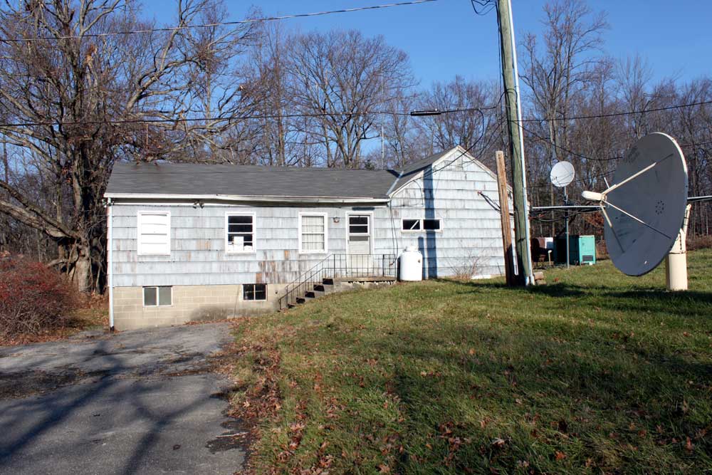
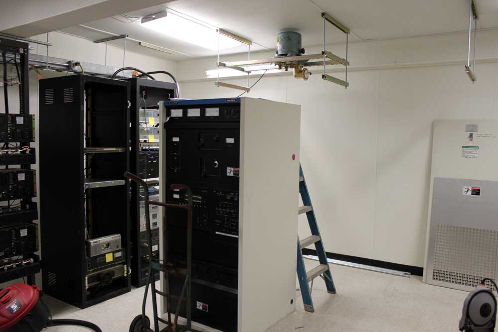
Blogging has been light due to workload being heavy, at the moment. We are engaged in moving transmitters out of this old house:

WINE 940 WRKI 95.1 former studio and transmitter site

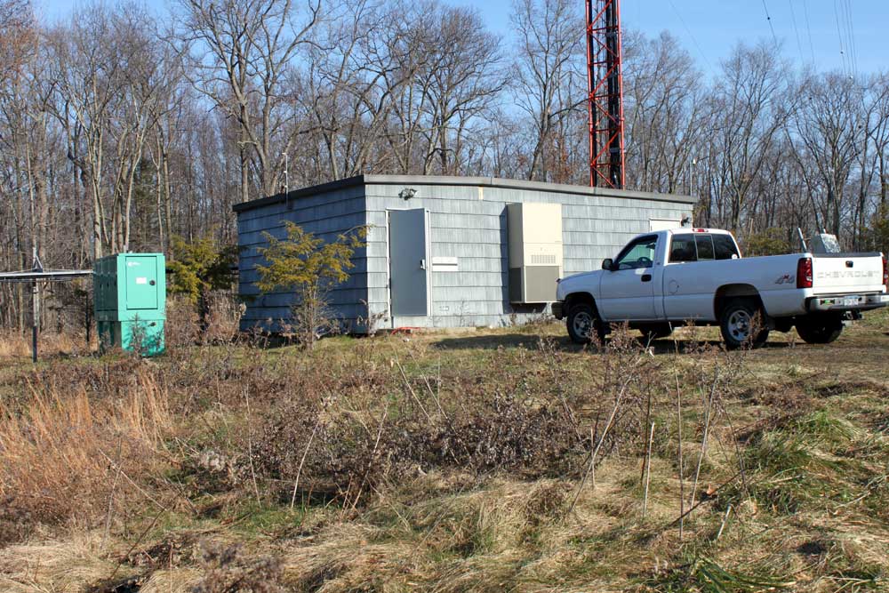
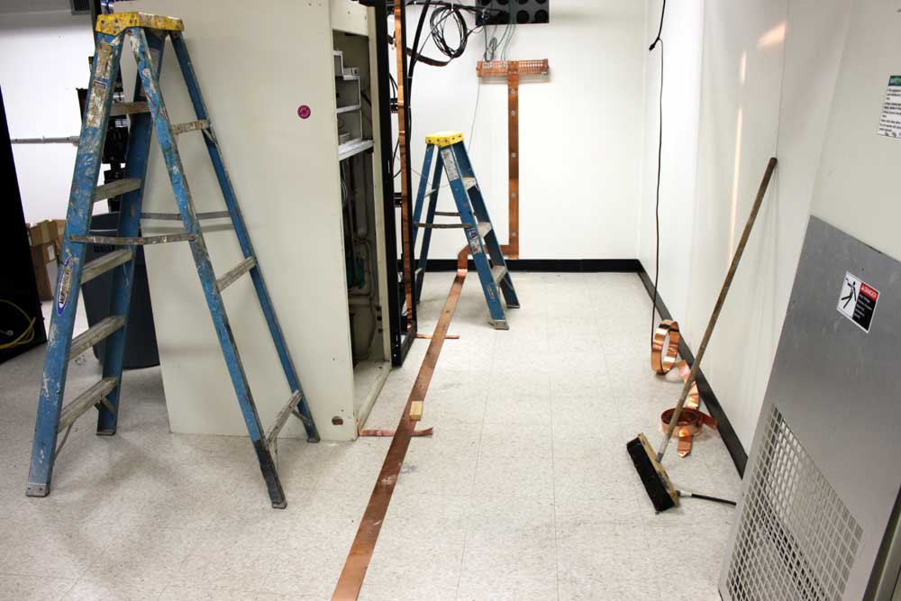
Into this new transmitter building:

WINE WRKI transmitter building at base of tower

The former building was the original studio for WRKI, 95.1 MHz, which signed on in 1957.  The co-located AM station, WINE 940 KHz, did not sign on until 1963.  As such, the building is a little worn around the edges, so to speak.  The FM transmitter has an auxiliary cooling device, for those hot summer days as the building itself is un-airconditioned:

WRKI Harris FM25K transmitter, circa 1986

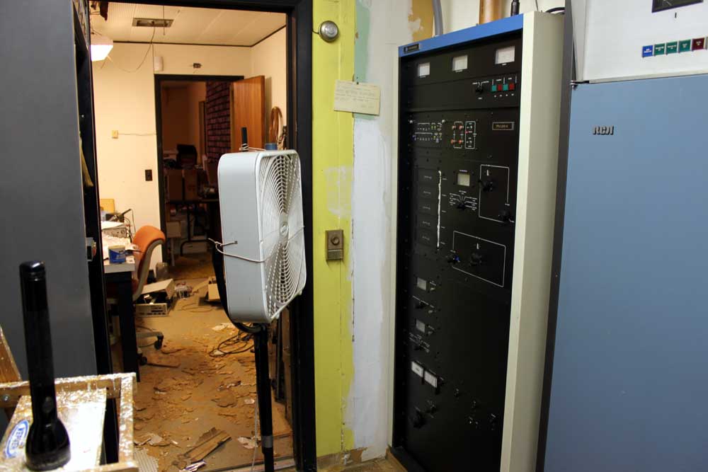
The rest of the building is in similar condition.  Ceiling tiles are falling off the ceiling and getting ground into the floor, junk is piled up in almost every corner, rodent feces, and the basement, don’t even get me started on the basement.

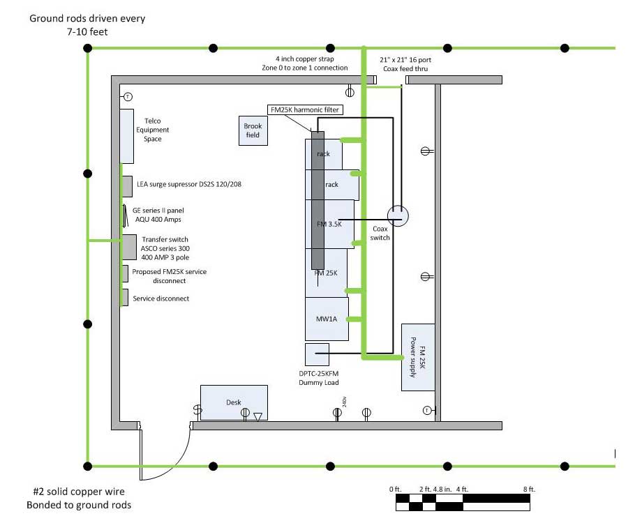
The basic floor plan for the new building is simple:

WRKI WINE transmitter room floor plan

Right now, the preliminaries are being done, mounting the coax switch, running conduit, pulling wires, etc.

A few design notes:

  1. This building is much closer to the tower, which is sited on a high hill (715 feet, 218 Meters) and sticks up 500 feet (152.1 Meters) above that.  Basically it is the area lightning rod, thus special attention will need to be paid to grounding and bonding.  I decided to isolate the electrical ground in favor of the RF ground for lightning protection.  This involves putting toroids on the electrical ground conductors.
  2. The building itself is shielded with continuous steel plating, but that has been cut in a few areas to install air conditioners.  Those areas will have to be repaired and the AC units bonded to the steel plate.
  3. Back up cooling will be in the form of a large exhaust fan and intake louver.
  4. The tower itself is AM radiator for WINE.  It is 170 degrees tall, which means high RF fields at the base, therefore good RF bypassing is needed.
  5. The transmitter room itself is fairly small for what needs to go in there. careful design and placement is required.

Here are some in-progress pictures:

WRKI backup transmitter, Harris FM3.5K, coax switch in the background

The first order of business was retuning a Harris FM3.5K transmitter to function as the backup. The current backup transmitter is an RCA FM20E, which no longer runs. After the move is completed, that transmitter will likely be scrapped.

I attached super strut to the ceiling at four foot intervals. I used this strut to support the 4 port coax switch. All coax in the transmitter room is 3 1/8 inch hardline, which has a power rating of 40 KW.  Since the transmitter power output is 20 KW, this leaves a lot of head room for problems.  When working with a 3 1/8 inch coax, it is important to remember to cut the inner conductor 1 1/2 to 1 3/4 inches sorter than the outer conductor, otherwise the stuff doesn’t go together right.

The 30 KW air cooled dummy load was moved up from the other building and connected to the coax switch.  This allowed the backup transmitter to be tested.

WRKI backup transmitter and dummy load

Three inch ground strap connects all the transmitters, racks, and dummy load to the station ground.

WRKI ground strap, new transmitter building

Electrical requirements are being met by a 400 Amp service backed up by a 120 KW generator.  Once the conduit work is finished and all the wires pulled, the coax to the old building can be cut and brought into the new building, then the station can go on the air with the “new” backup transmitter.

Good bye UHF RPU, we hardly knew you

As more and more things that use radio are invented, it is inevitable that the limited spectrum will be squeezed. We see this with BPL, which admittedly causes interference on the HF spectrum, however, proponents have deep pockets. Then there are the so-called “whitespaces” between active TV channels coveted by broadband providers.  Not even the once-sacred GPS system is immune to interference by other radio systems being implemented by companies who “bought” the radio spectrum in question. Although it is quite beyond me exactly how one can buy or sell radio spectrum. I suppose next they will be selling sunlight and rain.

The next chunk of the RF spectrum being repurposed is in the 451-457 MHz range.  This has already been eyed by the Department of Homeland Security for on-scene data communications networking.  However, the latest interested party is the Alfred Mann Foundation, which builds bonic implants.  In an interesting twist, one of the plans for the spectrum in question is something called the MMNS (medical micropower network systems).  This network would be used to transmit commands from the patient’s spinal cord to prosthetic devices.

Many TV stations use 450-455 MHz band for IFB and cueing.  Radio stations use that same spectrum for remote broadcast and telemetry return links from transmitter sites.  RPU frequencies used to be very congested, as remote broadcasts were often an additional revenue stream for radio stations.  These days, most stations to “cellphone” remotes, e.g. the disk jockey goes out to a store or event and calls it in on his or her cellphone.  Some of the more fancy stations use POTS codecs like the Comrex blue box or matrix and very few still use ISDN.  So the first question is how many broadcasters still use UHF (or even VHF) RPU gear (AKA The Marti)?

The second question is what type of damage or reaction could occur if a UHF RPU interfered with one of these MMNS devices?  Some RPUs use fairly high power levels and directional antennas.  But, according to FCC Report and Order on ET Docket 09-36, it is a done deal:

The rules we adopt will allow these new types of MedRadio devices to access 24 megahertz of spectrum in the
413-419 MHz, 426-432 MHz, 438-444 MHz, and 451-457 MHz bands on a secondary basis.

It goes on to say:

Each year, millions of Americans, including injured U.S. soldiers, suffer from spinal cord injuries, traumatic brain injuries, strokes, and various neuromusculoskeletal disorders. The devices that we anticipate will operate under our new rules are designed to provide artificial nervous system functions for these patients.

Which is nice.  I suppose if someone is at the mall setting up the Marti for a remote and when it gets turned on, Grandpa starts break dancing, one should find another frequency.  Do you think the DJs or promotions people remember that?  No, me neither.

If this keeps up, eventually everything is going to interfere with everything else and nothing will work.

Higashi no kaze ame

Or “East wind rain,” which was the Japanese code words transmitted to their embassies indicated hostilities with the United States were imminent. While the Navy intercepted the first message to the embassies, outlining the various code words and instructions on what to do when or if they were used, they never actually intercepted the code word messages themselves.

This is not all that unusual, as the Japanese were using several different diplomatic, army, and naval codes at the outbreak of the war.  Many different stations and frequencies were in use, and it is quite possible that the message was sent and never intercepted.  According to the NSA, many, but not all of the Japanese Codes had been cracked and were being read regularly.  The diplomatic code, known as Purple as well as a similar code, J-19, and a lesser version, JNA-20 were being intercepted and forwarded to Washington for decoding.  Only JN-25 was intercepted and decoded at Pearl Harbor prior to December 7th.

In 1979 the NSA declassified over 2,000 intercepts.  They declassified more in 1994.  Those decrypts paint an interesting picture of the lead-up and aftermath of Pearl Harbor.  A good book is “And I was There,” by Edwin Layton.  It was completed in the late 1980s before the 1994 document dump.  Layton was indeed at Pearl Harbor on the morning of December 7th.  Layton does not come out and directly say that Washington knew of the attack, but rather that they should have known, warned Pearl Harbor but didn’t.

By the first week of December, the Japanese tipped their hand several times.

  • A bomb plot message was transmitted to the Naval Attache in Pearl on September 24th.  This message was sent in J-19 and requested information on shipping and locations within Pearl Harbor-based on a grid.  No other locations around the Pacific required such detailed analysis by the Japanese Navy.  This was intercepted in Pearl but sent to Washington for decoding.  No information from this message was shared with the military commanders in Hawaii.
  • Several spies (Russian, British, Korean) and diplomats (Germany, Peru, Mexico) warned the US that the Japanese intended to attack Hawaii before the end of the year
  • The Japanese striking force did not maintain radio silence during its transit from Japan to Hawaii, they sent 663 messages, many of which were duly intercepted by Hawaii and the Navy intercept stations in the Philippines and Guam.  The National Archives contains about 100 of those messages, however, the direction-finding information attached to each message has been removed or remains classified.  In addition to this, most of the JN-25 messages sent between December 1-7 remain classified.
  • All PYB (long-range flying boats) patrols from the Aleutians were discontinued in early December.  Their patrol area covered at least part of the northern route from Japan to Hawaii.
  • On the evening of December 6th, Roosevelt was shown the first of 13 parts of a Japanese Diplomatic message which was a declaration of war on the US.  The US code breakers and translators finished the decrypt and had it in the hand of the President hours before the first bombs were dropped on Pearl Harbor, even before the Japanese envoys had read it.

It is also well known that Roosevelt wanted Japan to attack the US as justification for the entry of the US into WWII.  In early 1941, Roosevelt sent a gunboat up from the Philippines nosing around the Chinese coast to see if it could stir up any trouble.  The Japanese failed to take the bait on that and several other occasions.

December 7th, 1941
December 7th, 1941

There is still quite a bit of controversy as to who knew what and when.  Whether information was deliberately withheld, or not transmitted due to some concern of compromised intelligence or some bumbling bureaucracy is hard to tell.  Certainly, the powers that be in Washington knew more than they let on.  The military commanders on Hawaii took the fall and several thousand lost their lives that morning.  Many more would die in the coming months and the Japanese tide rolled over the western Pacific basin.

By the end of World War II, over 74 million people had died, most of them civilians.  History, do not repeat thyself.

The Gates BFE-50C Amplifier

Found in a pile of junk in the corner of an older transmitter site, this Gates BFE-50C or otherwise known as an M5675 Amplifier. This was used as an IPA in a Gates FM 1C transmitter installed around 1960 or so.  The rest of the transmitter has long since departed, likely to the scrap yard, however, somebody thought to remove this and set it aside.

Gates BFE-50C 50 watt VHF amplifier
Gates BFE-50C 50 Watt VHF amplifier

This unit is missing it’s grid tune knob.  The grid tune capacitor is still there, however.  There is also some evidence of heating on R403 and R407/408 likely due to a prolonged overdrive condition.  Otherwise, it is in good shape.

Gate BFE-50C 50 Watt VHF amplifier back

The design is pretty simple, a pair of 6146’s in push pull, three watts in nets about 50-60 watts out, according to the manual, which can be found here (.pdf).  The power supply voltages are fairly tame, 500 volts plate, 300 volts screen.  The one thing that this design does not have is any type of harmonic filtering.  When used with a larger transmitter, this makes sense because the transmitter output will have overall harmonic filters.  If this was to be used on it’s own for any reason, a good harmonic filter would need to be designed and installed.

Gates BFE-50C or M5675 50 watt VHF amplifier
Gates BFE-50C or M5675 50 Watt VHF amplifier

The schematic is straight forward.  Gates, the old Gates Radio of Parker Gates, designed good equipment.  Click on image for higher resolution.

Gates BFE50-C input section

It is a bit hard to see in this picture; the input section consists of three turns of #14 gauge wire coupled to two 4 turn sections of 14 gauge wire on either side of it.  This is matched to the grids Screen1 of the 6146s with C401.  L412, C411 and L413 form a low pass filter.  L412 consist of one turn #14 gauge wire, L413 is five turns of #14 gauge wire.  All coils are 3/4 inch in diameter.

Gates BFE-50C output section

The output section is even simpler, using just one loop of small diameter copper tubing.  The plate tuning is accomplished by C407, loading is C406.  Power output is adjusted by varying the screen voltage using R405.

Advantages of this design:

  1. The 6146 tube is fairly rugged, at class AB the 50 to 60 watt output range is well within the plate dissipation for a push pull configuration.
  2. No special parts are needed, everything can be found or fabricated by hand
  3. The 500 volt supply is fairly tame, maximum PA current should be less than 0.2 amps for 50 watt output and 50% PA efficiency.
  4. Output tuning and load allow for tuning into less than ideal loads, if required.
  5. If operated as a stand-alone unit, some type of plate current meter should be used to aid tuning.  A harmonic Filter would need to be designed and built for the output.
All in all, a pretty cool little FM amp.