Occasional reader Jeffery asks a good question, which I will attempt to answer here in simple terms. Phasing, when used with antennas, refers to the relationship that two or more radiating elements share with the waveform being transmitted. It is used to create an RF radiation pattern by adding energy to the wavefront in one direction by taking energy away from the wavefront in another direction.
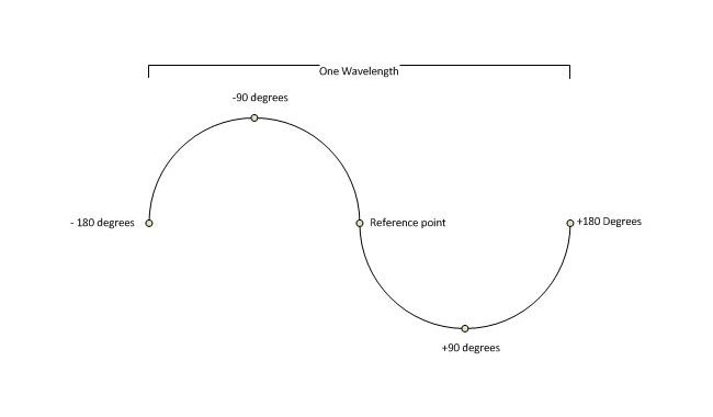
Phasing is often described as +/- X number of degrees from a reference point. Graphically, it would look like this:

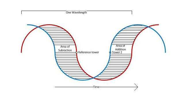
The reference point can be changed to any point on the waveform, in radio applications it is usually oriented around +/- 180 degrees. If the reference point is a single tower or element then this would be the end of the story. Add a second tower to this system and it would look something like this:

In this picture we have two waves being radiated from two separate elements. These elements are spaced 100 degrees apart and tower #2 is phased to +90 degrees. RF generator is coupled to both towers via a power divider, the reference tower (tower #1) is feed with 57% of the power that tower #2 is being feed. Thus, the ratio of power to the respective towers would be 57:42. Thus, if tower one had a power reading of 1.00, tower two would be 0.74. The towers are on a north/south line with the reference tower bearing 180° from tower #2. In the area of subtraction, the waveforms from each tower cancel each other out to some radiating less power toward the south; in the area of addition, the waveforms sum to create a more powerful waveform, radiating more power towards the north.
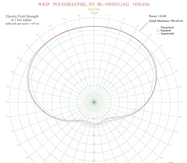
Resulting pattern (WKIP, Poughkeepsie, NY):

This is a typical two tower array, however, there are two slight differences; the reference tower is 215 degrees tall, tower two is 90 degrees tall. This is yet another use of “degrees” to relate electrical length or separations. The second, more notable distinction is that this array is Directional daytime, and non-directional night time, which is the opposite of most AM stations in this country.
Electrical height can also be described as a function of wave length, e.g. 1/4 wave, 1/2 wave, etc. Most AM towers in this country are 1/4 wave length, which equates to 90 degrees. Often, higher powered stations, and some low powered stations put up towers near 1/2 wavelength due to the better ground wave performance of those towers. At lower dial positions, a 1/2 wave tower becomes an expensive proposition due to the height required.
In theory, an unlimited number of towers can be used to create a pattern by introducing nulls (areas of subtraction) and lobes (areas of addition). In practice, the highest number of towers I’ve ever heard being used in an AM directional array is twelve; KFXR 1190, Dallas, TX. There may be others, too.
An excellent resource for AM directional antenna technical information is Jack Layton’s Directional Antennas Made Simple, which is out of print but available from various sources.
