Eventually, disaster will strike. It can range from a fire at the transmitter site to a tornado at the studio. Someday, every station on the air will be knocked off at the worst possible moment. It is the law of nature. Perhaps the most difficult disaster to recover from is the loss of a tower at a transmitter site. An FM tower holds the antenna, therefore, finding a tower or building nearby and placing a temporary antenna there will get the station back on the air in a reasonable fashion.
An AM tower is the antenna, which is much harder to replicate. One possible solution is to use a temporary wire antenna while the tower is being rebuilt. This is allowed in FCC 73.1680 emergency antennas, provided the commission is notified of the situation by informal letter. Directional stations must operate at 25% or less of the station’s licensed power, or demonstrate that radiation limits are not being exceeded in any direction. That usually can be accomplished by taking a set of monitor points.
A wire antenna can come in several configurations:
- The fastest to deploy is the random-length end-fed wire. This can normally be attached to the existing ATU and tuned up with components on hand. It requires having an OIB, generator, and receiver to tune, which not every station has. In addition to that, extra components may be needed in the ATU for tuning purposes.
- The next easiest is a tower-length wire ready to deploy. This is a length of wire equal to the height of the tower, with insulators and supports. The wire should be supported as high above ground as possible using trees, wooden poles, etc. Still requires having an OIB, generator, and receiver to tune. Likely to be within the tuning limits of the ATU components on hand.
- A 1/2 wave dipole tuned for 50 ohms. This can be connected directly to the transmitter output, thus is the best solution if the ATUs were damaged or otherwise not serviceable. In this situation, two 1/4 wavelengths of wire are coupled at the center using a 1:1 balun. Again, this antenna should be supported as high above ground as possible using trees, poles, and other non-conductive supports. Can be installed in a V, inverted V, or L shape as required.
All three of these choices would likely limit transmitter power output to 1-2 KW. Choice 3 likely represents the most efficient radiator and can be fabricated ahead of time and stored at the transmitter site.
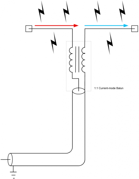
To make a 1/2 wave dipole, cut two lengths of wire using the formula L(feet)=246/F(MHz). This formula does not account for a velocity factor of 90%, which is typical for stranded wire. The reason is, since an MF dipole antenna is necessarily going to be lower than 1/2 wavelength, it is better to start the antenna a little long and trim it to size for a 50-ohm impedance. If commercially made insulators are not available, insulators can be made from non-conductive materials like PVC conduit, PEX, plexiglass, etc. The insulators on the ends of the wire need to account for the voltage peak that will occur there. If small “dogbone” type porcelain insulators are used, string three or four of them together using nylon or poly rope. The insulator needs to be able to withstand 8-10 KW of power under full modulation.
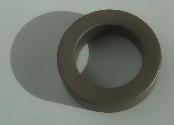
A 1:1 balun will distribute the RF currents evenly on both wires, which will help improve efficiency and coverage. Most Ham Radio Baluns are not designed to work below 1.8 MHz and therefore, will not work for this purpose. A balun can be made with a ferrite toroid made from 68, 73, 77, or type F material. A good choice would be Amidon FT-290-77 or FT-290-F. The type F material has a higher AL value, thus fewer turns are needed. In addition to that, high voltage insulated wire should be used to wind the balun.
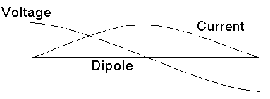
Since, in a 1/2 wave dipole configuration, the voltage is at a minimum at the center of the antenna, and current is at a maximum, some attention needs to be paid to wire size as well.
To give a good idea of wire sizes required, some basic information is needed. For a 1 KW station, it is assumed that the carrier will be modulated to 100 percent, therefore the peak envelope power will be 4 KW. If the station is asymmetrically modulated, add another kilowatt. Therefore, the maximum current formula is I=√(P/R). P is the power in watts, or 5,000 and R is the radiation resistance or 50 ohms, thus I=√(5000/50) or 10 amps. The maximum voltage is E=√(P x R) or E=√ (5000 x 50) or 500 volts. For a safety factor, multiplying these values by 1.5 is recommended. That will likely account for any impedance differences due to ground proximity and so forth. Therefore for a 1 KW station, the dipole antenna should be designed for 15 amps and 750 volts.
For a 2 KW station the peak envelope power for an asymmetrically modulated transmitter is 10 KW, thus it follows that 30 amps and 1500 volts are safe working figures.
With the proper torroid core, a turns count of 7-10 turns bifilar will suffice. Since it is a 1:1 balun, the turns count on both sides of the transformer will be the same. The balun then should be placed in a suitable water proof housing designed to be attached to the center of the dipole antenna. This is a good example of a commercially available 5 KW 1:1 balun for amateur radio use:
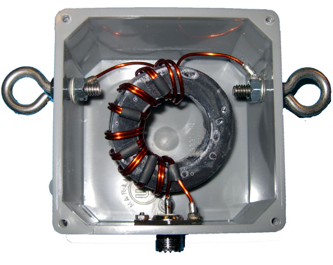
The antenna can be fed with RG-8, RG-8X, RG-8A, RG-214 or any other coax this is capable of handling the peak envelope power of the radio station. The connector can be UHF, N, LC, etc. In some cases, the may be easier to simply omit the connector and connect the coax to the balun using some type of strain relief on the cable coming out of the box.
Once this antenna is made, a bit of tuning may be required to bring it to 50 ohms. This can be done with a bridge and generator, or with the transmitter on low power. Either way, the measurements must be taken with the antenna at operating height as the distance to ground will effect the termination point impedance. It may require some trial and error.
In all, a good backup antenna can be made for about $50-60 or so. A little bit more if fancy transmission line is used. Well worth the expense and effort to have something ready to go in a moment’s notice.
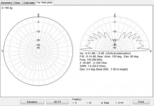
Update: I’ve been fooling around with this on EZNEC, it may not be that easy to do, especially with the lower frequencies in the AM band. The antenna needs to be at least 0.06 wave length above ground to perform correctly. Somewhat lower over better ground conductivity, e.g. ground radials. Even at this height, it needs to be lengthened significantly to get the feed point impedance close to 50 ohms.



Very useful for standby when main AM mast collapse !
@ Paul: Have you tried this 1/2 wave dipole in 1Kw transmitter yet or this from EZNEC ?
I’m going to make this type of AM antenna for our 610Khz transmitter site, please give me some experiences ? Thanks a lot !
Pham, I have used this style antenna two or three times on the AM broadcast band. Basically, they were used for several weeks while an old rusty tower was removed and replaced. They work well, but require careful tuning, especially at the lower frequencies. One time, it was a 1 KW station, thus I was able to run the transmitter at full power. The other two times, the station’s TPO was higher, so I ran those at 1,500 watts carrier power and reduced the modulation to 100% positive peak.
Thanks to Paul, it would be wonderful if you post some pictures about this type of antenna in working !!
Hola Mis estimados Colegas.
Tengo problemas con una radio de Am que se va a mudar de lugar.
Y los Radiales 360 Grados?.
Que hago con la protección a Tierra?.
Si pueden ayudarme con algunas fotos les agradezco mucho.
Perdon aparece estafa pero relamente no se como aparecio es apalabra es (por favor),
necesito salir con una radio urgente.
$50-$60? With your tower down, how are you going to raise the center of a 1/2 λ antenna high enough? We speak of an inverted V that has arms ~ 75 meters long. R U saying that U have a spare tower high enough for that, but not 75 meters high up to support a 1/4 λ vertical wire? To be sure U cud run a horizontal 1/2 wave dipole at 150 meters length. But do you have that kind of real estate? And do you have a multitude of supports to raise the horizontal dipole high enough over the ground? The expense seems to me to be substantial for your support structures, whatever they may be. U must have some plan for your supporting structure(s). I am curious as to what it is.
In any situation that requires an emergency replacement antenna, a fair amount of imagination, creativity and improvisation will be required. Support structures are where you can find them, there is no one sized fits all answer.
Hi Paul,
I made a wire dipole FM transmission antenna. Instead of using a manufactured balun I made 7 wire loops of coax and tightly bound them in line with plastic ties. Have you seen this done? It seems to work well for me.