Update: What? Nothing Happened! Something I think any radio engineer can appreciate, the incoming magnetic field from the flare was not polarized for maximum effect. According to NOAA Space Weather Prediction Center, the incoming particles were parallel to the earth’s magnetic field, and thus blocked. In order for storms to have major effects, they need to be cross-polarized with the earth’s magnetic field. Learn something new every day.
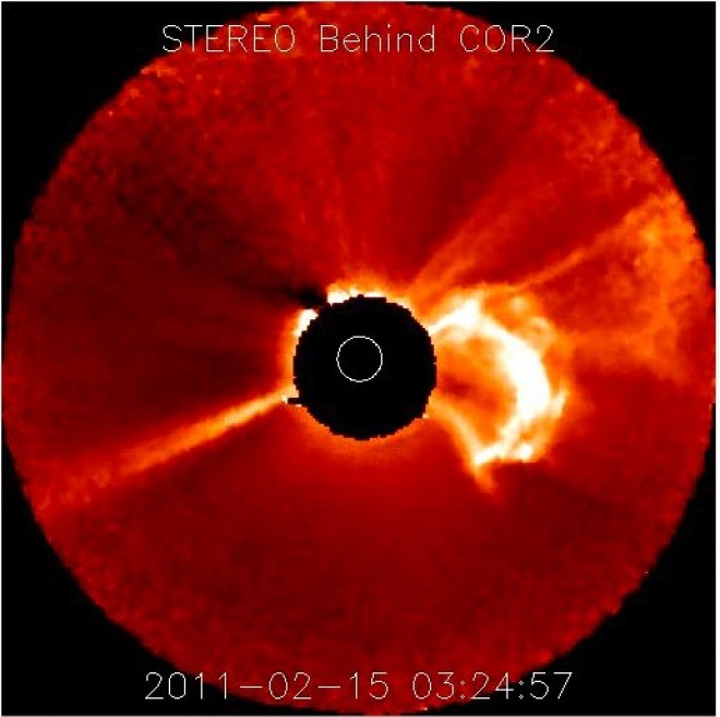
On February 15 at 01:50 UTC, a massive flare erupted from the sun. Classified as an X2.2 storm, it is the largest since December 2006. The 2006 storm disrupted GPS, and some satellite signals and caused 950 mHz STLs to burp occasionally. With all of the cellphone systems synced to GPS, not to mention things like HD Radio exciters, it could be an interesting day. Or not. Already, some reports are trickling in from southern China of communications disruptions.
Feb 15 0150 UTC solar flare
According to NOAA Space Weather, there is a 45% chance of geomagnetic activity starting on Thursday, February 17th. It is noted that Geomagnetic storms reaching the G1 level and radio blackouts reaching the R1 level are to be expected. Mid to high-level latitudes may see extensive aurora borealis, which will be visible in spite of the full moon.
All of the programming elements, all of the engineering equipment and practices, all of the creative process, the music, the talk, the commercials, everything that goes out over the air should reach as many ears as possible. That is the business of radio. The quality of the sound and the listening experience is often lost in the process.
Unfortunately, a large segment of the population has been conditioned to accept the relatively low quality of .mp3 and other digital files delivered via computers and smartphones. There is some hope however; when exposed to good-sounding audio, most people respond favorably, or are in fact, amazed that music can sound that good.
There are few fundamentals as important as sounding good. Buying the latest Frank Foti creation and hitting preset #10 is all well and good, but what is it that you are really doing?
There was a time when the FCC required a full audio proof every year. That meant dragging the audio test equipment out and running a full sweep of tones through the entire transmission system, usually late at night. It was a great pain, however, it was also a good exercise in basic physics. Understanding pre-emphasis and de-emphasis curves, how an STL system can add distortion and overshoot, how clean (distortion-wise) the output of the console is, how clean the transmitter modulator is, how to correct for base frequency tilt and high-frequency ringing, all of those are basic tenants of broadcast engineering. Mostly today, those things are taken for granted or ignored.
Audio frequency vs. wavelength chart
Every ear is different and responds to sound slightly differently. The frequencies and SPLs given here are averages, some people have hearing that can go far above or below average, however, they are an anomaly.
Understanding audio is a good start. Audio is also known as sound pressure waves. A speaker system generates areas or waves of lower and high pressure in the atmosphere. The size of these waves depends on the frequency of vibration and the energy behind the vibrations. Like radio, audio travels in a wave outward from its source, decreasing in density as a function of the area covered. It is a logarithmic decay.
The human ear is optimized for hearing in the mid-range band around 3 KHz, slightly higher for women and lower for men. This is because the ear canal is a 1/4 wavelength resonant at those frequencies. Mid range is most associated with the human voice and the perceived loudness of program material.
Bass frequencies contain a lot of energy due to the longer wavelengths. This energy is often transmitted into structural members without adding too much to the listening experience due to a sharp roll-off starting around 100 Hz. Too much base energy in radio programming can sap loudness by reducing the midrange and high-frequency energy from the modulated product.
High frequencies offer directivity, as in left right stereo separation. Too much high frequency sounds shrill and can adversely affect female listeners, as they are more sensitive to high-end audio because of smaller ear canals and tympanic membranes.
Processing programming material is a highly subjective matter. I am a minimalist, I think that too much processing is self-defeating. I have listened to a few radio stations that have given me a headache after 10 minutes or so. Overly processed audio sounds splashy, contrived, and fake with unnatural sounds and separation. A good idea is to understand each station’s processing goals. A hip-hop or CHR station obviously is looking for something different than a classical music station.
For the non-engineer, there are three main effects of processing; equalization, compression (AKA gain reduction), and expansion. Then there are other things like phase rotation, pre-emphasis or de-emphasis, limiting, clipping, and harmonics.
EQ is a matter of taste, although it can be used to overcome some non-uniformity in STL paths. Compression is a way to bring up quiet passages and increase sound density or loudness. Multi-band compression is all the rage, it allows each of the four bands to react differently to program material, which can really make things sound differently than they were recorded. Miss-adjusting a multi-band compressor can make audio really sound bad. Compression is dictated not only by the amount of gain reduction but also by the ratio, attack, and release times. Limiting is relative to compression, but acts only on the highest peaks. A certain amount of limiting is good as it acts to keep programming levels constant. Clipping is a last resort method for keeping errant peaks from affecting modulation levels. Expansion is often used on microphones and is a poor substitute for a well built quiet studio. Expansion often adds swishing effects to microphones.
I may break down the effects of compression and EQ in a separate post. The effects of odd and even order audio harmonics could easily fill a book.
Not to take anything away from Gary Breed, K9AY, who makes and sells these things under the corporate name AYTechnologies, I decided to make my own K9AY antenna system and controller. Basically, after looking at the currently available commercial version, I figured I could make a better unit for less money and be happy.
The basis for the K9AY antenna is that it has a steerable null. The gain around the antenna is close to unity, except for the terminated side of the loop, which has a deep null. This can be switched around using a combination of relays that change the loops and termination. This comes in very handy for MW and SW listening when co-channel stations can create annoying interference and heterodynes. I have had good success pulling many stations out of the muck, especially in the AM band using this antenna.
This antenna requires a good ground to work against. For optimum installations, I would recommend placing two radials under each side of the loops. This will keep the ground conductivity below the antenna fairly constant, thus the value of Rterm will remain consistent for each band.
My other idea is to add a preamp right at the antenna to overcome transmission line loss and the loss from a 4 port passive receiver coupler. Something around 10 dB, low noise (obviously), low parts count, and rugged. I decided that a Norton preamp was a good design, with only one active device, a common 2N5109 BJT. Most of the time, this preamp is switched off and out of the circuit. There have been several occasions, however, where an extra 10 dB made the difference between no copy and good copy.
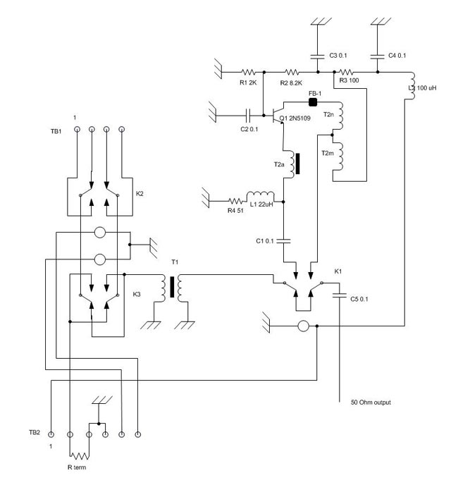
This is the schematic of the relay board and preamp combined:
K9AY antenna controller with preamp
The parts list is as follows:
Symbol
Part
Symbol
Part
C1 – C5
Ceramic 0.1 uf capacitor
R1
2 Kohm ¼ watt
FB-1
Ferrite bead, Amidon FB-43-101
R2
8.2 Kohm ¼ watt
K1 – K3
Omron G6K-2F-Y small signal relay
R3
100 ohm ¼ watt
L1
22 uH ¼ watt
R4
51 ohm ¼ watt
L2
100 uH ¼ watt
T-1
9:1 balun
Q1
2N5109 w/heat sink
T-2
Norton feedback trans
The 2N5109 transistor is a CATV unit and it has a 50 input and output, that reduces the number of impedance transformers required. The value of Rterm is determined by which band one wants to operate on. I used Omron G6K series low signal relays. Again, because this is a receive only antenna, those relays will work well.
Terminal board connections, TB1:
Terminal
Use
1
SW loop
2
SE loop
3
NW loop
4
NE loop
Wire loops go between Terminals 1-4 and 2-3.
Control terminal board connections, TB2:
Terminal
Use
1
Preamp power
2
Rterm
3
Rterm ground
4
Ground
5
Relay 2
6
Relay 3
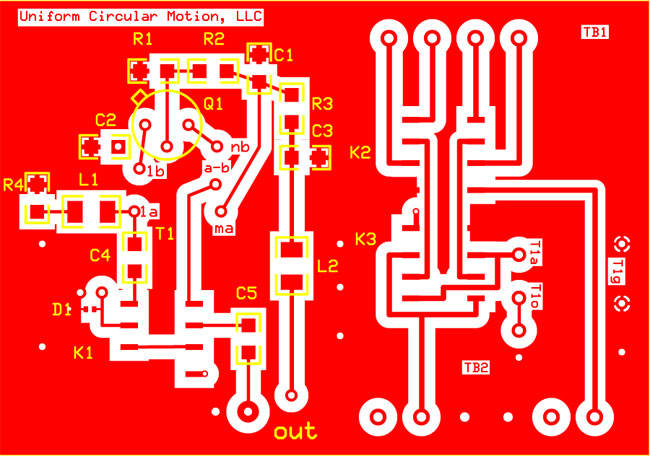
To create a low noise preamp, I decided to use surface mount devices and to try and make all the traces as close to 50 ohm impedance as possible. I created this SMT-printed circuit board:
SMT K9AY board, not to scale
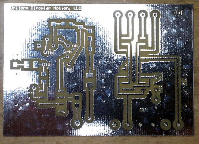
From this, I ordered 6 boards from PCB express:
K9AY PCB
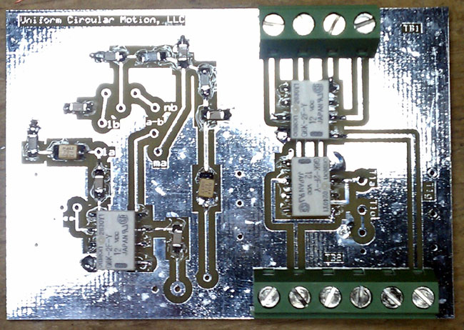
This is the board with all passive components installed:
K9AY loop antenna control board partial
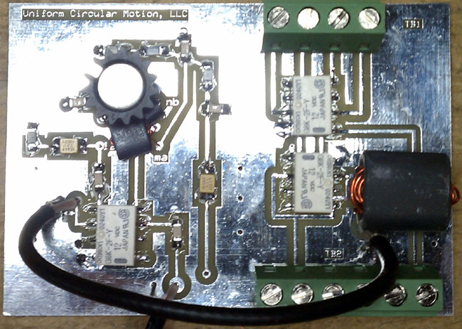
This is the board completed:
K9AY antenna control board completed
My current K9AY is an amalgamation of parts removed from various equipment. The relays are large, 12 VDC units which do not have the best contacts. It works well enough, but I’d love to get one of these units into the control box at the base of the antenna. Unfortunately, my antenna field is still in about 18 inches of snow, so it will have to wait until some of the snow melts off.
I would position this antenna as far away from transmit antennas as possible to avoid overloading the preamp and or causing problems with the switching relays. For the average amateur set up, 75 to 100 feet separation should be more than enough.
You know those fancy new facilities pictures with the accompanying article you can normally find in the trades? The article usually expounds on how this guy made the decisions on purchase then these guys worked hard and pulled it all together. Here is the work hard and pulling it all together story.
WEBE and WICC have been in the same studio building for several decades. The Pacific Recorders and Engineering equipment, while great, is tired and worn out. On top of that, an F1 tornado ripped the AC units off the roof last June, ripping the membrane and doing extensive water damage to the facility.
The cleanup/water damage mitigation took some time. All of the carpet and ceiling tiles needed to be replaced. The walls needed to be resurfaced with new drywall. In some cases, modifications such as removing a storage closet from the engineering room, moving a door, and building a new talk studio and WICC control room needed to take place. In short, lots of dust, dirt, and disruption to the station equipment and staff. It has not been trouble-free, as several times computers and consoles failed due to age and dirt.
Sometime about the beginning of December, new equipment and furniture began to show up and the project was underway.
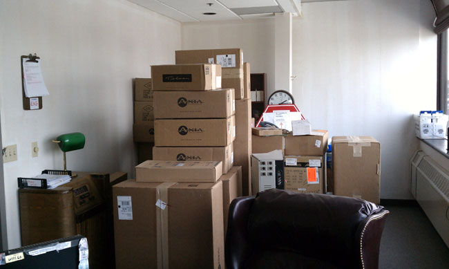
Cumulus Bridgeport new equipment
All of the new equipment was stored in the program director’s office. Heh, the program director’s office.
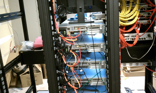
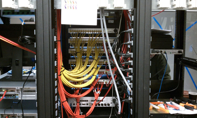
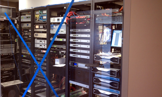
Cumulus Bridgeport new rack room
A new rack room was designed around the old one. The old racks are out of the picture to the left. The original rack room had a door into the hall, that has been replaced by viewing windows, the door has been moved to the engineering office, next door. I kind of like the windows, it lets visitors see the fancy computers but keeps them out of the room itself.
Cumulus Bridgeport Op-X servers
The existing automation system is being replaced by Op-X. This is the business end of the Op-X audio servers. All of the network connections are Gigabit using Belden Mediatwist (1872A) Category 6 cable.
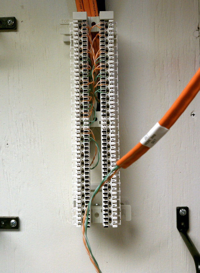
Cumulus Bridgeport wire wall
All the wiring from the studios and racks are brought to this wall. The terminations are Krone LSA-PLUS blocks. AES/EBU digital and analog audio is run on Category 5e cable.
Cumulus bridgeport wire wall Krone block
Krone LSA-PLUS termination block with Belden Mediatwist cable. All rack and studio wire runs are terminated on this style block. Notice the wire labels, every run is labeled with both termination ends and use. Mediatwist cable is fairly easy to work with, the pairs are bonded, so a special tool is recommended to quickly separate the wires.
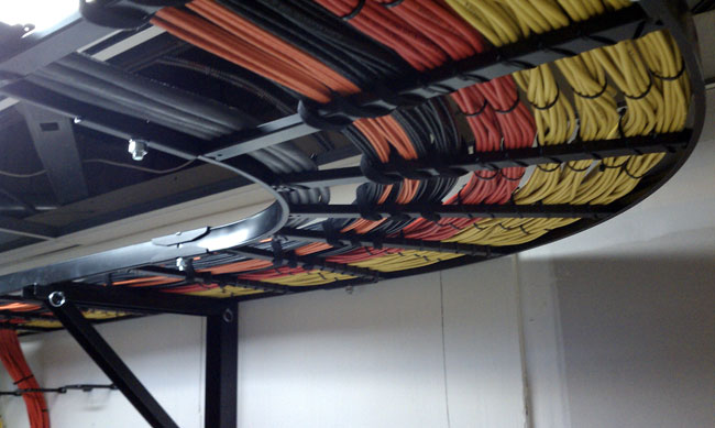
Cumulus Bridgeport wire tray
Wire tray between the racks and wire wall.
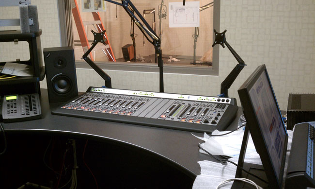
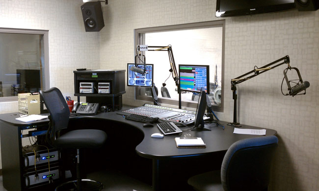
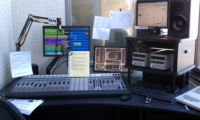
WICC new Axia console installation
The new WICC control room and talk studio. The Axia consoles are pretty slick. They are not a true mixing console in the traditional sense, they are more like a control surface. Most all of the audio inputs are in the rack room, however, the microphones are digitized in the studio and sent over an IP network to the rack room. All input and output channels are computer configurable and remote controllable. Console inputs also have onboard mic preamps and full processing.
Cumulus Axia console set up
Axia console control software.
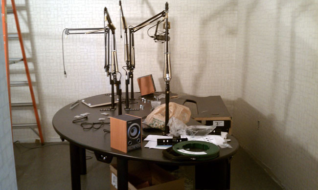
New WICC talk studio furniture
The new talk studio set up. This is located where the news room used to be. In order to stay on the air and maintain the old studios, a sort of musical chairs system needs to be played. In the end, the WEBE studio and one production room will end up where they started, everyone else will be in a new space. The news room will end up where the current WICC control room is.
Cumulus Bridgeport network switches
Network audio switches.
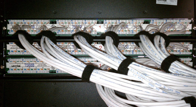
Cumulus Bridgeport network patch pane
Network patch panel, notice the T568B markings.
Currently, the program directors are loading all there material in the Op-X system. The time schedule is to transfer WEBE into a temporary studio in about two weeks.
More updates as the project progresses.
Update: The new Axia equipment and Op-X automation is on line as of 2/24. More pictures to follow.
WICC studio is nearly done, just a few odds and ends here or there. This is located where the former talk studio was located.
WICC talk studio
WICC talk studio, host and four guest positions. This is located where the former news room is.
Former WICC air studio, gutted
This is the former WICC control room. It has been gutted and several walls are being removed. This will become the permanent WEBE control room when it is finished.
WEBE temporary control room
WEBE temporary control room.
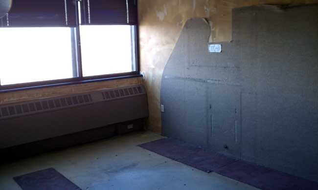
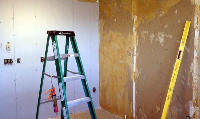
WEBE old control room, gutted
The former WEBE control room, gutted. All the carpeting has been removed and 1/4 inch drywall is going over the old, glue encrusted drywall. This room will become a production room.
WEBE WICC rack room
WEBE WICC rack room viewed from the hallway, approximately where the door to the room used to be. The old racks to the left are being stripped out and removed. All of the stations are now on the air from the new racks.