Richard Dillman, who is the driving force behind the Maritime Radio Historical Society (MRHS) has produced a show on KWMR called “Incredible Radio Tales.” This is a show that talks about the various sounds heard on the radio, both natural and man-made. Many of the shortwave frequencies are used for “utility” uses.
He does a great job explaining things like Skyking, numbers stations, and so forth. It is a great show, I can imagine this story being told on Halloween.
You can listen to the first episode here, it’s about an hour long:
I see this statement being made on various forums, blogs, and other places. As some would like to believe, the problem with HD radio is that people don’t like change. A Look at the early days of FM radio in the 1950s is a good example of this. FM radio took decades to catch on, HD Radio is no different. Currently, HD Radio is experiencing “growing pains” and the occasional “bump in the road.”
Except; no, not really.
Here is a side by side comparison:
Problem/issue
FM radio 1950
HD radio 2010
Implementation of technology
A new band was created and new radios containing the old (AM) and new FM band were manufactured. During the experimental phase (1937-47), the frequencies were between 42-50 MHz. This changed to 88-108 MHz in 1947. Uptake on new radios was slow due to a frequency shift.
Existing AM and FM frequencies were utilized using “Hybrid” mode. This entailed changing existing channel bandwidths arbitrarily. New receivers with the HD Radio chipset needed to receive broadcasts.
Funding
FM radio was implemented by broadcasters who, for the most part, bore the brunt of the costs themselves.
Consumers are generally unaware of HD. Those that are become disappointed with the lack of additional programming choices and poor receiver performance
Creation of interference
FM broadcasting created no interference to any other broadcasting station when it was rolled out
HD radio has created many interference problems, especially on the AM band at night, where skywave propagation makes adjacent channel stations bear the brunt of exceeded bandwidths. FM is prone to co-carrier interference from higher digital power levels created to solve poor reception issues in addition to adjacent channel interference to adjacent FM broadcasters from exceeded bandwidths.
Lack of consumer awareness or interest
HD radio offers a slight improvement to “CD quality” which is hard for the average listener to tell apart from typical analog FM. AM offers increased audio quality over analog, however, due to reception problems, AM receivers often lose data synchronization and return to the analog signal, creating up/down listening experience most find annoying.
Consumers were generally aware of FM radio, however, the FCC created a major stir when forcing FM broadcasters to move from their original frequency band of 42-50 MHz to 88-108 MHz. This move rendered obsolete many FM radios and caused hard feelings to amount early FM radio fans.
Technical reception problems
FM stations began broadcasting with low power levels and horizontally polarized antennas. Radio was not yet a mobile medium. Many FM listeners needed to install outdoor antennas on their homes to get reception. Radio listeners were willing to undertake this for good reception.
HD power levels are less than needed to have reliable reception in buildings and mobile listening environments. A 6 to 10 dB increase has not effectively been implemented nor solved the problem
Audio quality
FM broadcasting is markedly superior to AM broadcasting in the areas of noise reduction and fidelity.
HD radio offers a slight improvement to “CD quality” which is hard for the average listener to tell apart from typical analog FM. AM offers increased audio quality over analog, however, due to reception problems, AM receivers often loose data synchronization and return to the analog signal, creating up/down listening experience most find annoying.
Auxillary services, additional channels
FM broadcasting did not have any such features in 1950
HD radio offers the choice of 2 additional channels for programming. These channels are taken from the existing bandwidth/bit rate of the digital carrier and are a lower quality than the main channel. In addition to that, there is a data channel that can be used to display song titles and such
Programming
HD Radio main channel is the exact duplicate of its analog signal. HD-2 and HD-3 channel offer a variety of programming choices including simulcasts of AM stations, retransmissions of co-owned out-of-market stations, syndicated satellite programs, and occasionally a niche format.
During the early FM development and implementation, the only competing electronic medium was AM radio
Electronic Media availability
HD radio has enjoyed a rubber stamp environment where large businesses and the FCC work together to re-write interference regulations with no regard for technical consequences.
The choices of electronic media are wide and diverse. These include TV, satellite radio, internet, 3G wireless, mp3 players, AM and FM radio
Regulatory environment
The FCC staff was filled with ex or future RCA employees, who were interested in the status quo, thus keeping FM from becoming too big too fast and competing with the roll out of RCA’s television technology. Therefore it was hobbled with low power levels and a bizarre station class structure
The FCC staff was filled with ex or future RCA employees, who were interested in the status quo, thus keeping FM from becoming too big too fast and competing with the rollout of RCA’s television technology. Therefore it was hobbled with low power levels and a bizarre station class structure
The FM rollout in the late forties and early fifties is vastly different from the HD Radio rollout in the zero zeros. Due to fear of competition and patent disputes, RCA in conjunction with the FCC did all they could to squash the new technology. That is why FM radio took so long to be accepted by the general public. For those not versed with the history of FM development and FM broadcasting in the US, see Empire of the Air, by Tom Lewis. See also: Edwin H. Armstrong. It is a good read for those radio obsessed.
HD Radio is failing because the consumer is not buying it, I see little to change their mind.
Could be. Digital Radio Mondiale, or DRM, is a modulation scheme that a group of broadcasters and transmitter manufacturers have been working on since about 1997 or so. There are numerous shortwave broadcasters; the BBC, the CBC, Deutsche Welle, Radio France Internationale, the VOA, and others have been using DRM on shortwave for several years now. I can state that the shortwave DRM system works well, I have a software decoder and use the sound card input on my computer to decode and listen to DRM shortwave broadcasts.
The goal of DRM is to establish a worldwide open standard for digital broadcasting in the LF, MF, HF, and VHF bands. In the early years of development, DRM was designed for digital broadcasting on bands below 30 MHz. This system is now known as DRM30. Since then, the DRM consortium has expanded that to the VHF band (up to 174 MHz) as well (meaning where the current FM band is located) and has called that system DRM+.
DRM uses COFDM (Coded Orthogonal Frequency Division Multiplex) modulation, which is the same as IBOC HD radioTM. This is a robust modulation system that employs multiple carriers at lower power (than an analog carrier) spread across the entire allotted bandwidth.
One of the claims is DRM transmits less power and is more energy efficient. In general, digital radio modulation does transmit less power, that is true. However, transmitters have to be run more linearly for digital due to the increased bandwidth. This may not translate to greatly increased efficiency from the AC mains to RF standpoint. Because of that, there is more waste heat, and thus more air conditioning is needed to cool the transmitter room.
Some of the advantages of DRM over Ibiquity’s HD radioTM are:
Open source system. Royalties are paid by the transmitter manufacturers only (and to date, most major US transmitter manufacturers have already paid these). There is no royalties paid by the broadcaster to install DRM or by the consumer when purchasing a DRM-capable receiver. One company does not own the rights to the modulation system for all the broadcasters in the country.
Universally standard; accepted by the European Telecommunications Standards Institute (ETSI), International Electrotechnical Committee (IEC), and the International Telecommunications Union (ITU).
The CODEC is HE-AAC 4, which is widely used worldwide.
DRM30 and DRM+ fit into existing band plans and will not interfere with other users on adjacent channels. DRM30 is designed for 9 KHz channel spacing and DRM+ is designed for 100 kHz channel spacing, all of which comply with existing FCC regulations.
Standardized receiver profiles are things that must be included in all DRM receivers. There are several advanced options as well, such as a media-rich system that includes video.
DRM+ has several added features: DRM text, which is similar to RBDS. EPG or electronic programming guide, which shows what is coming up next and a searchable schedule of when programs may be heard out to seven days. Some DRM+ receivers will have a TIVO-like recording device that allows the user to record programs and playback later.
Traffic reporting and routing
In addition to that, DRM30 stations have the ability to transmit low frame rate H. 264 video. This is a distinct advantage for short-wave stations that are seeking a way around firewall blocking. The video image is small, 176 x 144 pixels and it is 8 frames per second, which is about as good as can be expected using a 9 KHz channel.
In some cases, DRM is capable of a hybrid mode (ed note: DRM calls this “Simulcast mode”), but what have we learned about hybrid mode digital radio: It doesn’t work very well. In short, it would be better if DRM were employed in the digital-only mode. To many, this is a distinct disadvantage, but I don’t see it that way. There have been many that have made the IBOC rollout/FM broadcasting rollout analogy. Frankly, those arguments don’t hold water. When FM was introduced, no attempt was made to shoehorn it into the existing AM (Standard Broadcast) band, it was not designed to interfere with other stations or itself, power levels were sufficient for good reception using existing technology, quality over AM was markedly improved and programming was often separate (simulcasting with existing AMs did not start until later). My point here is that any digital broadcasting should be introduced on a separate set of frequencies. Some have proposed using TV channels 5 and 6, which makes some good sense. Whatever the outcome is, we have learned, the hard and expensive way, that hybrid digital broadcasting does not work well.
A brief video about DRM30.
Currently, DRM30 is only allowed on shortwave broadcast frequencies in the US. I asked a product development engineer from a major reputable broadcast transmitter manufacturer about this, and his response was:
Medium-wave broadcasting in the US already has HD radio, so the FCC would be disinclined to allow a new standard
One might be able to apply for an experimental license to broadcast DRM, but it would likely have an expiration date
It is possible to operate DRM in a hybrid mode on the AM band and occupy the same bandwidth as HD radioTM (30 kHz), it might also be possible to squeeze that down to 20 KHz.
Most modern (read: solid-state) AM broadcast transmitters should be able to transmit DRM without modification (antenna systems may be a different matter).
It might be fun to apply for an experimental license to broadcast somewhere in the 1600-1700 KHz range with DRM30 only and no analog modulation, except for an hourly station ID in Morse. A 1/4-wave tower in the middle of that band would be 141 feet tall. With the use of a skirt, a grounded tower can be employed. That and a few above-ground radials and the system would likely be pretty efficient. Part of the experiment would include driving around and taking signal strength readings while recording the programming material. This would give some real-world testing on how the system would perform in widespread use.
Of course, this would require a major about-face by the FCC, which is not likely unless someone there grows or somehow acquires a backbone.
Some people question the need to do any type of digital broadcasting. I am a realist, in one way, shape, or form, digital radio broadcasting will (or already is) take(ing) place. It would make the most sense if the best system were used, which is not necessarily the first system proposed. The big question is, will today’s terrestrial broadcasters be involved, or out of business?
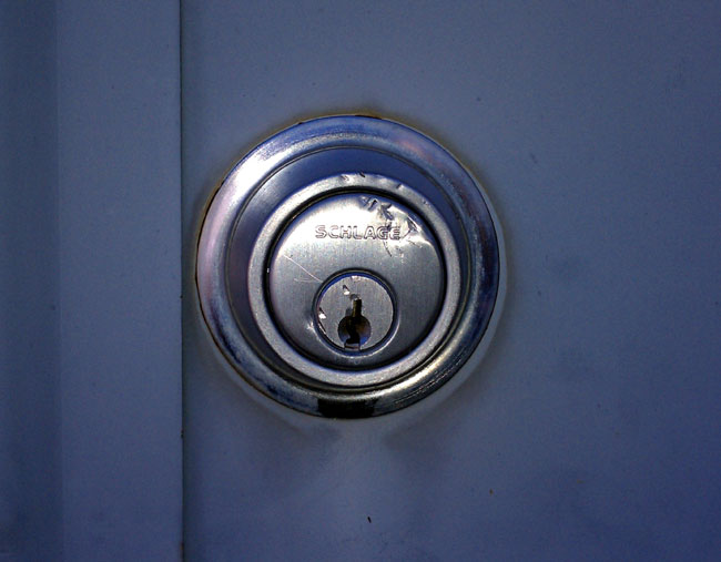
I was doing a weekly visit to one of our FM transmitter sites the other day when I noticed this:
Dented deadbolt lock at the transmitter site
Looks like somebody has been whacking the deadbolt lock with a hammer or a wrench or something. Pretty sure that was not like that the last time I was here. Time to get one of those IP cameras and set it up on the tower.