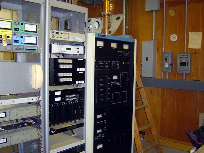
RCA BTF-20E

Does anyone need any parts for one? Long-time reader and commenter John has one that looks to be in good shape that he is willing to part with or part out.  I had three of these units in Harrisburg and my recollection is they were pretty solid units.  When tuned properly, they were low noise and sounded good on the air.

The one issue I had was with the small 100 pf pass-through/by-pass capacitors in the IPA.  Several went bad and were no longer functioning as bypass caps.  The result was the transmitter would self-oscillate.  I think there were seven or eight of them and I replaced them all at once.  The exact model of that particular transmitter was a BTF-20ES1, which was one of the last FM transmitters off of the factory floor before the broadcast division went under.
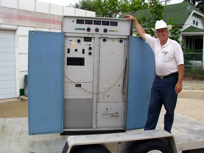
RCA BTF-20E FM transmitter
Late model RCA BTF-20E FM transmitter

John says:

If anyone needs parts out there, I will probably cannibalize this unit as I have just too many. The separate power supply is inside the garage along with the latest version of the harmonic filter entirely made of copper.

I don’t know if the entire unit actually runs or if it is parts only.  It certainly looks like a clean unit.  As I recall, Comark bought out all the RCA broadcast parts and service. Comark was then sold to Thomcast, which was sold to Thales which I think spun off its transmitter division to Grass Valley Group.  Grass Valley started by making TV master control switchers, routers, and other video equipment.

Anyway, if you are looking for RCA parts for FM transmitters, contact me, and I’ll put you in touch with John.

Downgrading AM stations

One of the AM stations around here that I am familiar with is considering a downgrade, which is to say reduce power and get rid of a directional antenna system in favor of a non-DA antenna.  In this particular case, it makes sense, as the station can co-locate with another AM that is closer to the COL by a good distance.  The coverage from the new site at reduced power looks to be a good fit.  If this can be arraigned, the AM station in question would lose a multi-tower AM antenna system that is 50 years old and all the attendant headaches, expenses, and labor that goes with it.

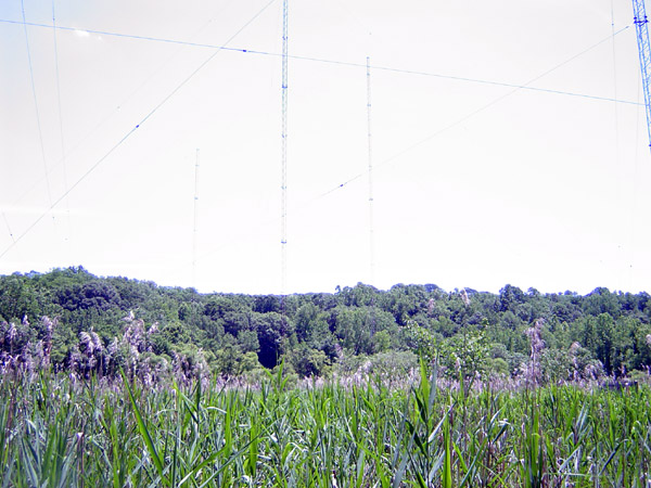
five tower directional AM tower array in a tidal swamp

Many AM stations that are DA-2 or even DA should consider downgrading to a lower power level and getting rid of their DA system.  Directional antenna systems on AM stations are maintenance nightmares.  Unfortunately, in the ’50s, 60s, and 70s, it was often thought that adding power, and extra towers to an AM station would give them great swaths of extra coverage.  Sometimes it worked out, sometimes it did not.  Often what happened was some area was added, but in areas that were nulls toward protected stations, signal strengths went down.  What the station ended up with was more towers, more maintenance, monitor points, a sample system, and more expense.

Taking an AM station in the other direction might actually make more sense.  Go back to one tower non-directional 1 KW or whatever power can be used in the daytime.  Time was when the FCC would only allow certain power levels; .5, 1, 5, 10, and 50 KW.  Those were what a new station had to work with.  No longer is that the case, any power level can be used so long as it meets interference contours and the city of license contour coverage requirements.

Presunrise authority is normally 500 watts and is available at 6 am, post-sunset authority varies but often a PSA extends the on-air time to 9 pm in the wintertime.  For a local radio station, which is what all but the class A AM stations are destined to become, this will be adequate.   For a losing station, it may be that, or turn in the license and sell the land to a developer.

Diplexing on another AM station’s tower closer to town is also a good way to get out of maintaining an expensive antenna array with diminishing income.

Something to think about.

Fireworks sychronized to music played over the radio!

In previous years, I have had the very pleasurable experience of setting up a fireworks show remote with music synchronized to our FM radio station.  Ordinarily, I don’t go near a remote broadcast, however, this is one of the more intricate broadcasts requiring coordination between the studio, the remote site, and the fireworks barge anchored 300 yards offshore, out in the Hudson River.  The fireworks company, Garden State Fireworks, are consummate professionals and produce a very well-choreographed show.

Giving them the synchronizing track on-site is not very hard, however, I was surprised to hear that not every radio station does that.  In fact, one of our, ah, ehm, Clear Channel competitors from The big Metropolitan Center Nearby could not be bothered to do it for the 4th of July fireworks this summer and last summer too.

The synchronizing track is on the left channel of a CD that Garden State Fireworks created, it is 1200 baud FSK data, 8,N,1, so it is pretty robust.

I thought I would post on how I do it and why. First of all, for the how part, there are two options:

  1. Play the music CD at the remote site and relay broadcast quality music back to the studio without any time delay.  Hard to do even with an ISDN line.
  2. Play the music CD at the studio and relay telephone quality audio for the firing track to the remote site from the studio.  Have the remote site play the air signal over the local PA system.

Option number 2 is technically far easier than option number 1, although it takes a fair bit of coordination.  Also, the sound reinforcement guy didn’t like the air signal idea because of the quality of the audio.   That is a little nit-picky, especially given the fact that much of the music at the fireworks show will be drowned out by the fireworks explosions.    In the end, he saw it my way.

Here is a list of equipment needed:

  1. Telco auto answer coupler, such as the Indy Audio
  2. Telco Hybrid, such as the Telos
  3. If the announcer is at the fireworks site, a POTS CODEC such as a Comrex Matrix or blue box
  4. Wireless microphone
  5. Telephone set and cord with RJ-11 connector
  6. Miscellaneous mic cables, power cords, etc
  7. At the remote site, two pots lines from the local phone company, long distance service as required.

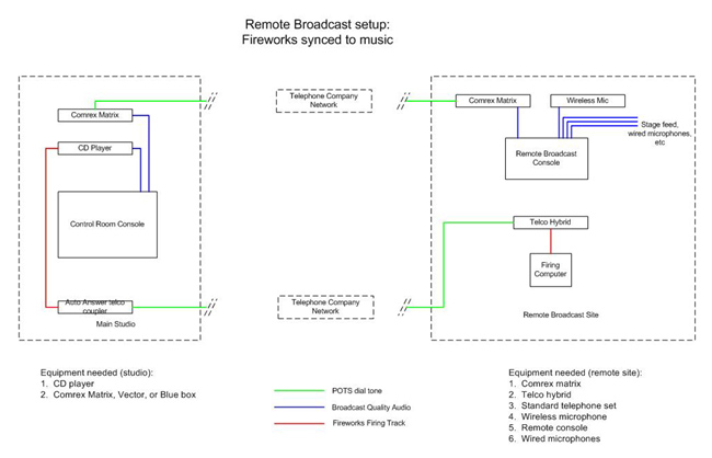
Here is the block diagram:

Note, this assumes no delay in the telco network, which under ordinary circumstances using the wired, not cellular network, there should not be any.  The touchiest part of the whole thing is getting the stage coordinated with the studio during the transition to the remote broadcast.  Once that is done, everything else just falls into place.

The firing computer is located onshore next to our broadcast booth.  They send the signal out to the barge on a wireless LAN link.

That is the how part.  Here is the why (the soundtrack is a little low):

That is from three years ago, but you get the idea.

Even though I don’t work for these people anymore, I asked if they needed help with the broadcast this year.  “Nope, we got it, thanks.”  I will be paying close attention.

Harris FM25-K

Old blue, I like to call them, the Harris 1980s model transmitters with black faces, white cabinets, and blue trim. I have yet to find one that I really like, the FM 25-K is, well okay. Sort of like that 200,000-mile jeep that works, most of the time, and it’s paid for.
This particular FM-25K transmitter is located at WIZN in Charlotte, VT.

Harris FM25-K transmitter

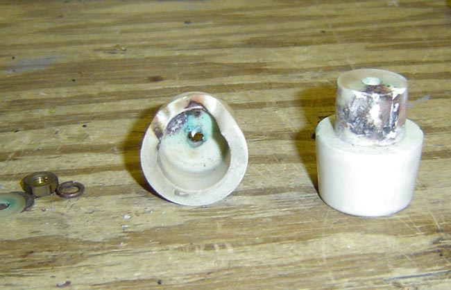
This transmitter was new in 1987.  It had a bad day yesterday, deciding to throw a temper tantrum and trip the HV power supply breaker.  Fortunately, the station has a backup transmitter.  When we arrived, we found the HV power supply feed through the insulator at E1 arced over and broken.  Again, fortunately, this station’s management believes in stocking spare parts and a replacement was on hand.

Harris FM25K HV power supply feed through insulator

This is part of the RF filter for the HV power supply. This happened once before, about two months ago. The replacement insulator then was used, so that might be a factor. Two months ago, both capacitors in the Pi filter and the HV power supply cable (RG-8 coax) were replaced all the way back to the rectifier stacks.

The FM25-K can produce spontaneous high-frequency oscillations if not tuned properly.  We looked at the transmitter output with a Rode Schwartz spectrum analyzer and found it to be clean.  Exactly why it blew out another feed-through insulator is a bit of a mystery.  Since the first replacement was a used part, we surmise that it may have been cracked.  If this replacement insulator arcs, there needs to be a full investigation.

As I said in the beginning, I have found these transmitters to be okay, not the best, not the worst.  Most of the problems I have encountered with the K series FM transmitters had to do with the controller cards.  There are two, one analog and one digital.  That’s what Harris calls them anyway.  Like the SX transmitter, and the MW transmitter to a certain extent, the control circuits are way over complicated and full of +/- 5 volt CMOS logic.   Having that type of control logic connected to a radio tower (e.g. lightning rod) is asking for trouble.