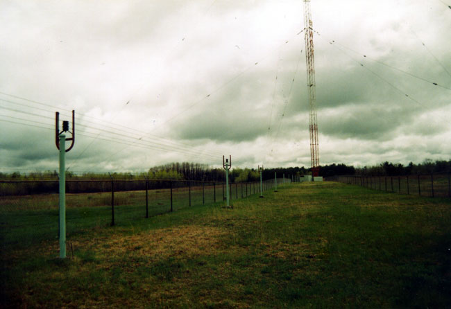
Partly for my own edification, partly just because, here is some information about AM antenna systems and their bandwidth. An AM tower is a radiator that, simply by the physical constraints of the tower structure itself, is pretty narrow-banded, even under the best conditions. Add to that, antenna tuning units, transmission line phasing, antenna phasing units, diplexing units, and things can get very squished outside of the immediate carrier frequency. This seems to be a particular problem with directional antennas, which most AM stations employ.

As an engineer, you can get some idea of how narrow an antenna system’s bandwidth is by looking at the base impedance measurement. Every AM station is required to keep the latest impedance measurement on file. When looking at these measurements, there will be one curve that indicates base resistance (R) and another curve that indicates reactance ( X, although often noted as + or -j). If the resistance and or reactance curve is slopped steeply at the carrier frequency and out to 20-30 kHz, it is a narrow tower. Add to that the different phase shifts of an ATU and or Phasor and things will be compounded. That is why it takes a professional to design and tune up these things, a poor design will never sound right.
Another way to get some idea of bandwidth requires a field strength meter. Modulate the transmitter with a 10 kHz tone at 50% modulation. Then, away from the near field, measure the carrier and 10 kHz +/- the carrier frequency on the log scale. The sidebands should be symmetrical and about 1/4 the carrier level.
Generally speaking, antenna systems need to be designed for low VSWR across the entire side band range (+/- 10 kHz from the carrier) as well as symmetrical distribution of radiated energy across the lower and upper sidebands. Several factors influence these conditions:
- Electrical tower height is perhaps the hardest thing to change once a tower is constructed. Short towers (less than 80 electrical degrees), or very tall towers, (taller than 200 electrical degrees) present problems. If one were constructing an AM station and could choose any tower height, something between 120 to 190 electrical degrees would be ideal. Existing towers can be top-loaded to add electrical height for an additional 30 degrees or so. Beyond 30 degrees it becomes difficult to physically attain and therefore impractical in most situations. Top loading and bottom loading of a tower can reduce bandwidth if done improperly. Bottom loading an AM tower is almost never done due to the very high voltage and current as the electrical length approaches 180°.
- Antenna matching networks can greatly improve or degrade bandwidth, depending on how they are designed. A T-matching network has more parts and is more expensive, however, it allows for optimum control over the R and jX phasing. This becomes much more difficult with directional antenna where phase considerations are a part of the station’s antenna field pattern development.
- Phasors present the biggest challenge, particularly in the power divider sections. A tank circuit power divider is the worst choice, and a shunt circuit power divider is the best bandwidth choice, however, it is the hardest to conceptualize.
Obviously, the more complicated the antenna system, the harder it will be to keep the bandwidth open over 20 kHz of spectrum. This is especially true on lower-frequency AM signals, where the bandwidth is a much larger percentage of the frequency. Multiple patterns, multiple tower DAs are a nightmare. Single-tower non-directional stations are the easiest to modify.
As far as the circuit itself, higher Q circuits have smaller bandwidths. Simply stated, in an alternating current circuit, Q=X/R. The better the reduction of X, which also has a lot to do with the relationship of the current and voltage phasing, the better the Q will be. This is why a T network is the best design for an ATU. With a 90° or 180° tower, this is relatively straightforward. In towers that are shorter or taller than that, it becomes more difficult as the value of R becomes less friendly.
In most cases, some sort of L/C network can be deployed to decrease the Q of an antenna system at the base of the tower. Directional stations also need to have the phasing equipment looked at, because, as noted above, certain designs can create bandwidth bottlenecks. All in all, it is usually an expensive proposition for a multi-tower directional station to broadband its antenna system. This is another reason why IBOC on AM is destined to fail, many AM towers cannot pass the extended sidebands adequately.
